


A bone screw is small, but the drawing may need to control several different geometries in a short length: a thread, a drive feature, a head, a tip, and sometimes a cannulated bore. Bone screw machining is therefore not just a turning problem. The manufacturing plan has to preserve the relationship between the screw’s axis, thread form, drive interface, and any internal feature while keeping the part identifiable through inspection.
This guide is about the supplier handoff and manufacturing decisions for a screw component. It does not specify a clinical design, implant performance, or regulatory acceptance. The released drawing and the device owner’s quality requirements govern each part. The aim here is to show which details should be explicit before a prototype or repeat order begins.
- Define the thread before selecting a process
- Keep the head and drive features aligned
- Treat cannulation as a linked feature, not a separate hole
- Specify material and condition precisely
- Inspect the form and the relationships
- Plan revision control for small parts
- Trace a feature problem from the part back to the setup
Define the thread before selecting a process
Threaded features can be described by more than a nominal diameter and pitch. The drawing may control the thread form, major and minor diameters, lead, length, runout, starting location, or relationship to a shoulder. Identify which characteristics are essential to the mating system and state the applicable standard or drawing-specific definition. If the thread is nonstandard, the model alone may not communicate the inspection method or acceptance boundary.
Different operations can create a thread, and the best route depends on material, size, quantity, geometry, and required evidence. Turning, thread milling, whirling, rolling, grinding, or another process may be considered by the manufacturing engineer. No single method is correct for every screw. The quote package should describe the required geometry and finish rather than prematurely requiring a process that may not fit the design.
Thread start and runout deserve attention. A sharp transition, incomplete first thread, or interference with the head can affect how a gauge or mating component engages. If the design allows a relief, specify its form and location. If not, show the intended transition clearly and confirm that the supplier can manufacture and inspect it with the selected route.

On a small turned part, a toolpath can form several features in one setup, but that does not remove the need to define how the thread relates to the head and tip. A drawing should identify the axis and the datum features that govern the screw as a whole. A part can have an acceptable local thread measurement and still be difficult to assemble if the axis or shoulder is not controlled.
Keep the head and drive features aligned
The head may include a drive recess, slot, hex, or other feature. Its geometry has to relate to the screw axis and the adjacent shoulder or bearing surface. If the drive is machined in a second operation, the setup must locate the turned body repeatably. The drawing should state the required angular or positional relationship where it matters, rather than leaving it implicit in the CAD model.
Review the minimum wall around the drive feature and the transitions from head to shank. A deep recess can leave little material at its base; a small corner radius may be difficult to machine or inspect. These are design-for-manufacturing questions, not invitations to change the design without approval. The supplier should identify a concern and request a controlled decision from the design owner.
Concentricity and runout may matter between a threaded section, shank, head, and tip. The drawing should define the relevant datums and geometric controls. The required verification method depends on the form and tolerance. Where the feature is too small for a standard gauge or probe, the buyer and supplier should agree how evidence will be produced before the first build.
Treat cannulation as a linked feature, not a separate hole
Some screw designs include a central bore. Its diameter, depth, straightness, location, and relationship to the external geometry may be important to the part’s intended interface. The drawing must identify whether the bore is through or blind, how its entrance and exit are treated, and which dimensions or geometric controls apply. A generic hole callout may not describe the required relationship to the thread or tip.
Deep or small bores can raise process and inspection questions: tool access, chip evacuation, breakthrough location, burr formation, and the method used to confirm the internal feature. If the drawing includes a cross-hole or intersects a thread, clarify how the intersection should appear and which edge conditions are acceptable. A section view can make the intended geometry easier to interpret.
For prototypes, confirm whether the first part needs to reproduce the final bore or only evaluate external fit. If the feature is simplified for an early sample, record that limitation. Otherwise, teams may compare a prototype with a production drawing and misread the result as evidence that the complete internal geometry has been verified.
Specify material and condition precisely
Medical screw programs may use titanium alloys or stainless steels, among other material options, but the exact grade and condition must come from the design documentation. A supplier should not replace a specified grade with a broad family name or assume that two materials are equivalent. State the required form, condition, documentation, and any approved substitution process on the purchase package.
Material identity should follow the stock through cutting and machining. If the order requires lot traceability or material records, define those requirements before the quote. The record should remain associated with the finished parts in the way the customer quality system specifies. This is especially important when multiple small part numbers or revisions are processed together.
Material choice also affects the machining plan, tool selection, edge condition, and finish. Those decisions should be based on the actual grade, geometry, and volume. The site’s medical titanium machining page y medical materials guide discuss broader considerations; the released drawing and customer requirements still control the screw.
Inspect the form and the relationships
Inspection should cover the characteristics specified on the drawing: thread form and size, overall length, head and drive geometry, shank diameter, tip, bore where present, and any required surface condition. The measurement system should be appropriate to the feature. Thread gauges can provide a functional check for defined thread requirements, while optical or coordinate methods may help characterize certain dimensions. The chosen plan must reflect the actual tolerance and acceptance criteria.
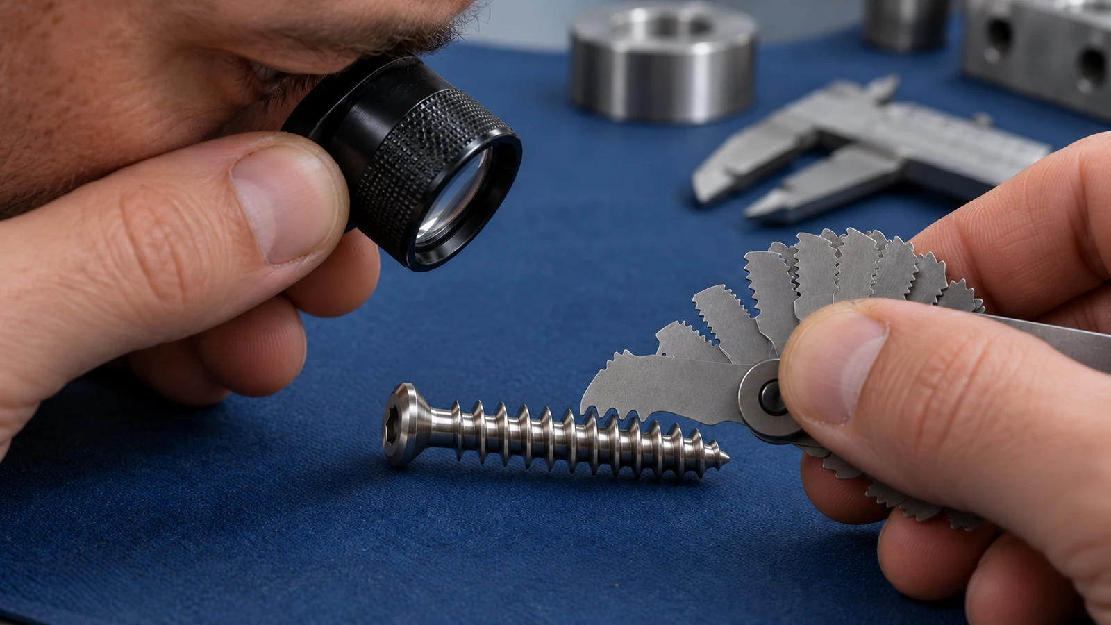
Do not rely on a single overall-length measurement to prove that all sections are correctly positioned. A screw may meet its length but have a shoulder or thread start at the wrong location. Datum references help separate those conditions. Likewise, a bore diameter check alone does not show whether the bore is aligned with the external axis.
Deburring and cleaning should be included in the manufacturing plan when specified. A burr at a thread start, drive recess, or bore entrance can interfere with assembly or obscure inspection. After secondary operations, check the features they could affect. Identify whether the report represents the as-machined condition or the final delivered state.
For a first article, select a manageable list of critical features that demonstrates the part matches the released drawing. Record the inspection method, part revision, and material identity required by the buyer. A dimensional report is evidence about measured characteristics; it is not a substitute for the device owner’s validation or use approval.
Plan revision control for small parts
Small screws can be easy to mix when several lengths, thread variants, or revisions look alike. Use clear part identification, controlled travelers or equivalent production records, and packaging that keeps variants separated as required by the order. The drawing revision and purchase order should match the model and inspection program used for the build.
When a design changes, check whether the change affects only the thread or also the head, drive, tip, bore, material, and inspection method. A revised thread length may require a different toolpath and gauge; a changed head can affect how the part is held for the secondary operation. Record the impact before reusing the previous setup or report template.
For low-volume builds, a flexible setup can support development, while repeat orders may benefit from a more stable method. The choice should follow the program’s quantity, revision rate, and evidence needs. The site’s medical precision parts design and manufacturing page gives a broader view of how component geometry and manufacturing scope come together.
Trace a feature problem from the part back to the setup
When a small screw misses a requirement, begin with the characteristic and its datum rather than changing the toolpath immediately. This short diagnostic table helps separate a drawing ambiguity from a process or measurement issue.
| Observed issue | First review | Useful next question |
|---|---|---|
| Thread does not gauge as expected | Thread definition, gauge type, start and runout | Are the drawing and gauge checking the same requirement? |
| Drive recess is off-axis | Secondary setup location and datum transfer | How was the turned body re-established in the fixture? |
| Cannulation appears displaced | Bore setup, breakthrough, and measurement access | Is the requirement position, straightness, or both? |
| Burr remains at an edge | Operation sequence and deburring instruction | Does the drawing define the edge condition after finishing? |
Keep the disposition attached to the part revision and inspection record. Do not revise an acceptance criterion during troubleshooting without the design owner’s decision. Bone screw machining becomes more repeatable when the drawing connects the thread, head, drive, tip, and bore, and the process review traces each measured result to the setup and datum that produced it.

