For broader context on medical-device prototyping and production planning, see the medical device industry page.
The shaft is a moving interface, not an empty tube
A laparoscopic instrument shaft may look like a long metal tube, but the assembly depends on more than its outside diameter. Depending on the instrument design, the shaft can guide a jaw mechanism, carry an internal rod or cable, provide a path for fluid or suction, connect to a distal tool, and engage a handle or rotation feature. A small change in straightness, bore condition, port position, or end geometry can affect how those parts fit together.
Laparoscopic instrument shaft machining is therefore best planned from the interfaces at both ends and the features along the working length. Start with the proximal connection, distal end, and internal passage requirements. Then establish how each port, slot, flat, cross-hole, or thread is located relative to the shaft axis. The design and manufacturing route should follow the approved drawing and intended device architecture; instrument designs differ, so no single feature set applies to every shaft.
- Map the shaft features to their mating parts
- Plan around length, slenderness, and support
- Keep ports and slots tied to the shaft axis
- Coordinate material, finish, and cleaning
- Verify the assembled interfaces, not only the tube OD
- What to provide for a shaft prototype or production quote
- Preguntas frecuentes
Map the shaft features to their mating parts
A feature map helps prevent a long part from being reduced to a single diameter check. Identify the handle connection, the distal component, the working channel or inner mechanism, and any external feature used for rotation or orientation. Establish the shaft axis as a meaningful reference and relate the end features and openings to it. If a shaft includes a keyed flat or angularly oriented port, define how its clocking is controlled.
| Shaft feature | Interface question | Manufacturing or inspection focus |
|---|---|---|
| Proximal end | How does it join or rotate within the handle? | End diameter, flat, thread, slot, or joining land per drawing |
| Distal end | How does it locate the jaw, tip, or other end assembly? | Concentricity, end form, attachment geometry, and burr control |
| Side ports or windows | Do they align with an internal channel or mechanism? | Axial position, angular orientation, edge quality, and internal deburring |
| Inner bore or liner | What must pass or move through the shaft? | Bore size, straightness, finish, cleanliness, and continuity if specified |
This drawing review often reveals that a seemingly simple part contains multiple inspection datums. A straightness requirement may relate to the outer axis, while a side port is controlled from an end face and an angular datum. The supplier needs to know which relationships are critical and how they are measured. Do not infer a clinical function or performance claim from the part geometry alone.
Plan around length, slenderness, and support
Long slender workpieces can deflect under tool pressure, vibration, or clamping. As the length-to-diameter ratio increases, stable support and a suitable sequence become more important. The machining plan may use guide support, staged operations, specialized workholding, or a route that separates rotational and cross-feature operations. The appropriate method depends on material, wall thickness, length, and feature access.
Thin-wall tubing introduces another tradeoff: the part must be held firmly enough to cut, but not squeezed enough to ovalize. The drawing should control roundness or diameter only as required for assembly, and the fixture should support the workpiece over enough length to reduce local deformation. When a shaft is cut from bar or tube stock, specify the incoming condition and any straightness expectation that affects machining allowance.
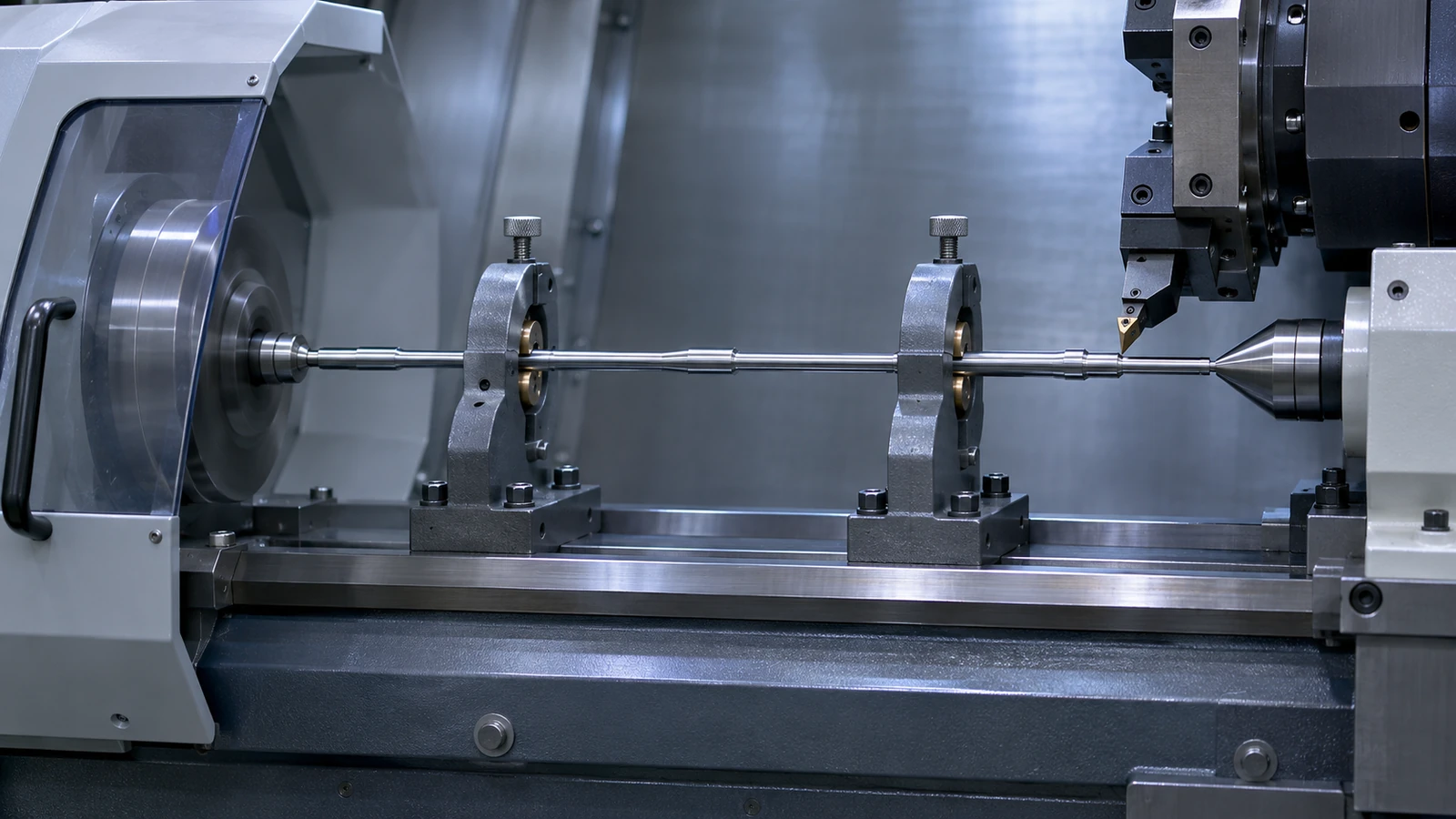
Operation order matters. Turning the outer profile before drilling an internal passage can make the part easier to handle, while cross holes or slots may need a later indexed setup. If several features must be clocked to one another, the process should preserve that angular relationship across operations. A datum mark, fixture key, or machine indexing strategy can help, but the method should be included in the process plan and verified on the first sample.
Keep ports and slots tied to the shaft axis
Ports, windows, and slots can create burrs on both the outer and inner surfaces. A burr on the inside may be difficult to reach and can interfere with a moving internal member, retain debris, or violate a specified cleanliness condition. The drawing should call out the edge condition and any critical internal surface. “Deburr all edges” is not sufficient if the exact break, radius, or finish affects a mating mechanism.
Feature orientation is equally important. If two ports are not in the same plane, their clocking should be defined relative to a clear reference. If a window must align with a distal tool or an internal channel, inspect position and orientation together. A feature can be correctly located along the shaft but still be rotated incorrectly around it.
Where the internal bore is functional, decide how it will be checked. A pin or mandrel may confirm passage at a defined size, while a visual method may be needed to inspect a local edge or port intersection. The chosen check should correspond to the drawing requirement; one method does not automatically validate bore straightness, surface finish, and cleanliness at once.
Coordinate material, finish, and cleaning
Material selection follows the approved design, intended use, sterilization or cleaning conditions, mechanical loading, and any required documentation. Stainless steels and titanium alloys are common engineering choices in medical instrument components, but grade and condition must come from the customer specification. Material machinability, work hardening, burr formation, and finishing response should be considered together with the geometry.
Surface requirements should distinguish functional areas from cosmetic ones. A sliding interface or inner bore may need a specified surface condition; an external finish may serve a different purpose. If passivation, electropolishing, or another finish is specified, identify the process, treated boundaries, and dimensional checks after finishing. Do not treat a general “medical grade” label as a substitute for a material grade or surface requirement.
The site’s mecanizado de acero inoxidable y titanium machining pages can support a material-route discussion. The surface finishing capability is relevant when a drawing requires a post-machining treatment. Material certification, cleaning, and packaging should follow the customer’s specific purchasing and quality requirements.
Verify the assembled interfaces, not only the tube OD
A complete inspection plan may include outer diameter, straightness, end features, port location and orientation, internal bore, thread or attachment interface, and surface condition. Decide which dimensions require a report and which can be checked with an in-process gauge. Measuring the part while it is clamped can hide deflection, so final verification should use the specified free-state or fixture condition.

A prototype build can test whether the proximal and distal components engage correctly, whether the inner mechanism moves through its intended range, and whether the shaft fits within the assembly envelope. Record the setup, mating parts, and revision. A fit check does not establish clinical suitability or device validation; it answers only the engineering questions included in that test.
For repeat orders, trace the measurement report to the material lot, drawing revision, and process revision. A change in tube wall, port position, alloy, or finishing route may require a different inspection plan. Keeping those records connected makes engineering changes easier to evaluate.
What to provide for a shaft prototype or production quote
Send a revision-controlled drawing and 3D model, material and condition, shaft length and wall details, quantity by phase, finish, and inspection/documentation requirements. Identify the inner passage, ports, slots, clocking features, proximal connection, and distal interface. State whether the sample is for dimensional review, handle fit, distal assembly, or another specific engineering purpose.
Ask the supplier to review workholding, feature sequencing, internal deburring access, cleaning, and measurement method before quote approval. If the design is changing, mark the open items and identify which revision is authorized for prototype production. This prevents a promising sample from being evaluated against an outdated drawing.
Preguntas frecuentes
Is every laparoscopic shaft a simple hollow tube?
No. Designs vary. Some include internal channels, slots, cross holes, flats, or attachment features, while other shafts serve different functions. Use the controlled drawing to define the actual geometry.
How is a long shaft kept from bending during machining?
The method depends on length, diameter, wall thickness, and material. Stable support, appropriate clamping, staged operations, and a sequence that limits cutting forces can help manage deflection.
Why does port clocking need its own control?
Axial location does not define angular orientation around the shaft. When a port or slot must align with another feature, the drawing should specify the clocking datum and inspection method.
What does a shaft prototype prove?
It can answer the stated fit, geometry, or mechanism questions under the test setup. It does not automatically validate the finished medical device or every intended use.
A well-planned shaft keeps the end connections, long axis, internal passage, and side features tied to one controlled datum scheme. That is the difference between making a tube-shaped part and manufacturing a useful instrument component.