

Bringing a complex hardware product to market successfully requires navigating structured validation gateways that verify physical scale, electronic integration, and structural durability. Developing a physical rapid prototype design model allows mechatronics groups to identify layout errors and refine spatial architectures progressively. Early design phases focus primarily on establishing spatial relationships, while later stages simulate real manufacturing properties to satisfy regulatory bodies. Progressing through these distinct developmental tiers ensures functional assemblies transition seamlessly into mass production without expensive retrofits.

Sourcing physical replicas that match intended series-production tolerances represents a mandatory requirement for high-end automotive, medical, and aerospace engineering. Project managers balance budget constraints with material fidelity, coordinating diverse fabrication methods from additive printing to multi-axis CNC milling. Meticulous physical testing sweeps confirm mechanical clearances, sealing performance, and assembly drop-durability. Structural designers verify fastening safety margins, parting lines, and draft angles to prepare the product architecture for mass molding.
Table of Contents
1. Conceptual Validation and Proof of Concept Stages
2. Form, Fit, and Aesthetic Works Like Integration
Conceptual Validation and Proof of Concept Stages
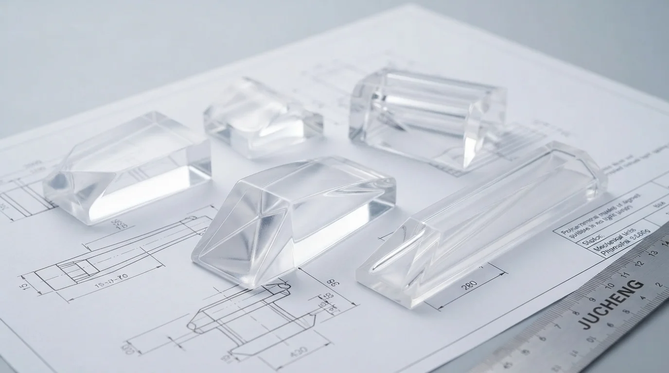
Question: Why are low-fidelity concept models critical during initial engineering cycles? Concept models validate volumetric proportions and mechanical space claims quickly, preventing fundamental architectural errors before heavy engineering begins.
Initial design exploration begins with low-fidelity proof-of-concept (POC) mockups to establish volumetric scale and check component spacing. Engineers execute a basic rapid prototype design model using fast FDM 3D printing or clear SLA resins to validate ergonomic layouts in real-world environments. Cosmetic finishes are secondary during this phase, as the primary objective is verifying basic spatial clearance inside tight structural cavities. Catching critical spatial interferences at this early stage prevents expensive downstream redesign loops.
Component spacing within complex assemblies is evaluated physically to ensure internal printed circuit boards fit without pinching wire harnesses. Simple conceptual models allow industrial design departments to pitch bold structural styles to project sponsors with minimal capital expenditure. Early physical confirmation clears a direct pathway toward high-fidelity functional integration trials.
Form, Fit, and Aesthetic Works Like Integration

Question: How is fitment verified for complex multi-part enclosures? High-fidelity visual and works-like mockups combine multi-axis CNC milled metals and cast polyurethane to replicate exact assembly parting lines.
Moving beyond spatial layouts requires high-fidelity mockups that simulate both cosmetic appeal and mechanical interaction. Implementing comprehensive rapid prototyping design principles allows engineering groups to produce works-like assemblies that actuate smoothly under hand-applied forces. Parting lines, battery covers, and functional buttons are hand-fitted meticulously to eliminate micro-gaps. Technicians apply custom soft-touch coatings or high-gloss automotive paints to duplicate retail-ready textures perfectly.
Sourcing optical-grade clear polymers like PMMA or polycarbonate replicates transparent visual screens and complex light pipe assemblies. Chemical vapor polishing eliminates internal microscopic milling tool marks to restore pristine, light-transmitting clarity. This table compares physical expectations across distinct prototyping stages:
| Validation Phase | Material Fidelity | Surface Finish | Primary Engineering Goal |
|---|---|---|---|
| Proof of Concept | Low (FDM, SLA resin) | Sand-sanded matte | Volumetric clearance check, spatial layout |
| Works-Like / Looks-Like | Medium-High (CNC, Cast Polyurethane) | Retail-grade texture, painted | Ergonomic hand feel, marketing displays |
| Engineering Validation | Maximum (Production-grade alloys, resins) | Passivated, anodized, textured | Environmental baking, dynamic stress tests |
Dynamic fitment checks are performed to verify interlocking snap-fits and structural rib deflection limits. Fabricating these complex components using genuine engineering polymers like Delrin or glass-filled Nylon ensures realistic flexing without micro-cracking. Mechanical teams confirm coordinate alignment repeatabilities before cutting permanent steel mold blocks.
Pre Production Validation and Regulatory Testing
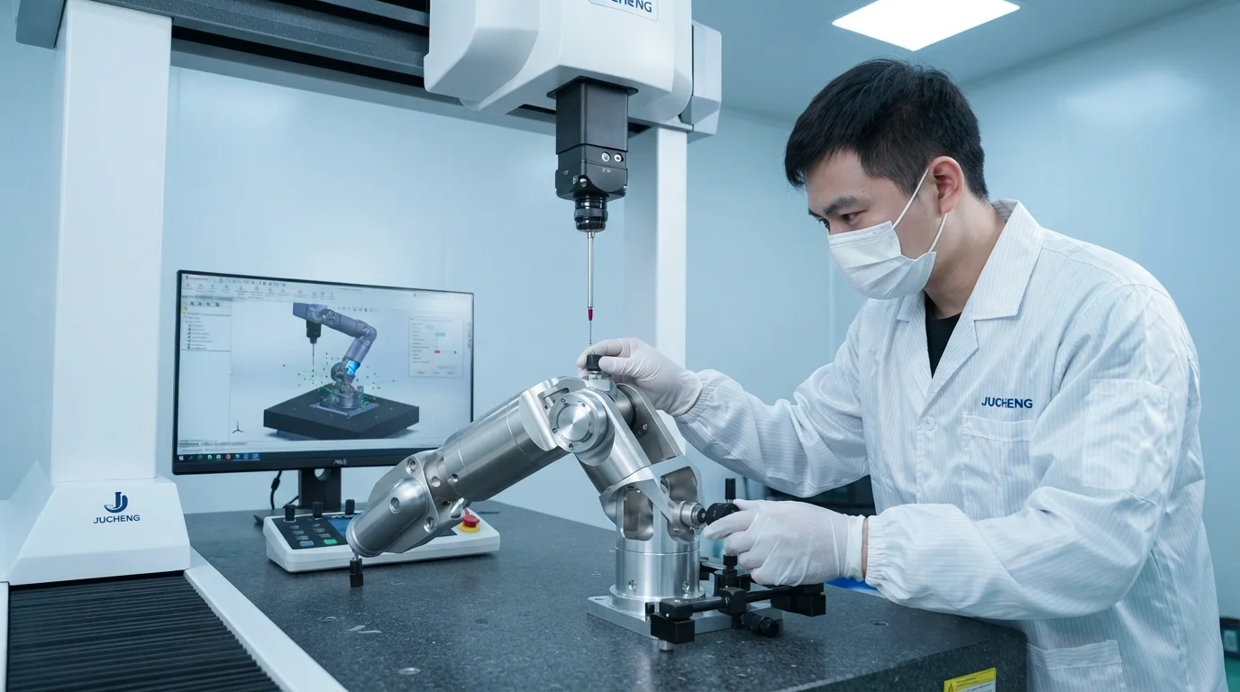
Question: What is the purpose of EVT and DVT phases before production? Engineering validation tests subject production-material parts to rigorous load, environmental, and regulatory certifications to identify tooling risks.
Preparing for commercial scaling requires rigorous validation of component durability under extreme operational stresses. Production-material parts fabricated through multi-axis CNC milling or rapid injection molds undergo Engineering Validation Testing (EVT). Physical assemblies are placed inside environmental ovens to verify thermal expansion coefficients and prevent fluid seal bypass. Structural linkages suffer high-impact drop and vibration testing to confirm mechanical safety limits.
Successfully executing a high-precision rapid prototype design model during Design Validation Testing (DVT) clears the final hurdle before shipping the product. Jucheng Precision operates a fully equipped manufacturing setup containing 150+ CNC machines, including 25 high-precision 5-axis Haas/Mazak machines to mill complex structural linkages. Standard coordinate measuring machines verify sub-micron dimensions to guarantee compliance with ISO 9001 and ISO 13485 guidelines. Sourcing high-fidelity pre-production parts prevents tooling reworks and protects launch budgets.
Factory engineers deliver exhaustive 24-hour free DFM analyses to resolve draft angles, ejector locations, and gating marks before mold core cutting begins. Specialized rapid tooling molds deliver injection-molded components within 4 to 15 days, minimizing the downtime between engineering revisions. Operating under a strict no-MOQ policy enables mechatronics groups to refine customized hardware variations safely.
Frequently Asked Questions (FAQ)

What is the main difference between an EVT model and a Looks-Like model?
EVT models are fabricated from actual production-representative engineering materials like Al7075-T6 or glass-filled Nylon to validate mechanical fatigue. Looks-Like models utilize cosmetic-grade casting polyurethanes or SLA resins primarily to evaluate form, color, and texture.
Can FDM printed parts be utilized as Works-Like prototypes?
FDM printing provides fast concept parts but lacks the isotropic strength and surface flatness required for high-stress Works-Like evaluations. Engineers specify CNC machined or rapid tooling parts to ensure assemblies withstand dynamic functional testing safely.
Why is coordinate metrology inspection critical for pre-production models?
Automated Coordinate Measuring Machines detect microscopic dimensional deviations that could cause sealing bypass or mechanical binding. High-precision inspection verifies the rapid prototype matches design specifications exactly before cutting production-grade mold plates.


