A fuel injector body may look like a compact turned component, but its manufacturing risk often sits inside the part: a small passage, a crossing hole, a seat, or an edge that is difficult to see after machining. A part can pass an outside-diameter check and still leave a burr in a flow path or place a sealing feature out of relationship with the connector end.
Automotive fuel injector body machining therefore needs a feature-by-feature plan. The goal is not to make every surface equally polished; it is to preserve the interfaces and internal geometry defined by the drawing, then choose an inspection approach that can actually verify them. This is different from a fuel rail: the rail distributes fuel to multiple injectors, while the injector body is the individual component that houses the specified injector features. The distinction also makes this a useful companion to Jucheng’s automotive fuel rail machining overview.
Which features define the body
Injector-body drawings can combine cylindrical locating surfaces, connector or mounting features, sealing seats, cross-drilled passages, threads, and interfaces to other injector elements. The exact arrangement varies by design. A supplier should not infer the function of an undocumented surface from a generic injector picture; the released drawing, model, material callout, and acceptance requirements define the part.
Separate functional features from handling or cosmetic surfaces. A connector interface may control fit; a seat may establish a seal; a passage can define where fuel travels; and a mounting diameter may locate the body in a larger assembly. The drawing may control some characteristics through size tolerances and others through geometric tolerances. Reading both is essential because a diameter can be within size while its axis or position is wrong.
Before machining, make a feature map: list each critical interface, its datum reference, the operation that creates it, and the method that will verify it. If a sealing surface depends on a turned axis, plan to preserve that axis through the sequence. If the design uses an intersecting hole, include the intersection and its edge condition in the review instead of treating the two drilled features separately.
Treat intersecting passages as a system
Internal channels are often the hardest features to inspect after the part is complete. When passages intersect, material can remain at the junction or an edge can carry a burr into a narrow path. The appropriate removal and verification method depends on passage size, geometry, material, and the drawing’s acceptance criteria. A generic “deburr” instruction may not explain how the internal edge should be reached or how the result will be confirmed.
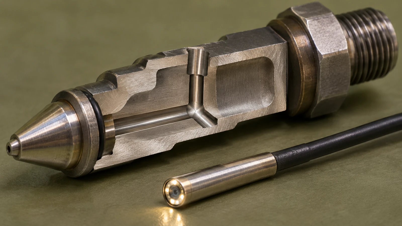
Plan the order of drilling, cross-hole creation, deburring, and cleaning together. The sequence should provide access to the intersection and avoid pushing debris into a blind region that is difficult to clean. For features that are inaccessible to a direct visual check, define whether inspection uses a borescope, optical method, flow check, representative section, or another approved technique. Each method answers a different question; none should be assumed to prove all passage dimensions and conditions.
Technical application notes on machined fuel-injection holes describe how intersecting passages can create burrs and why inspection access matters. That is a useful reminder to specify the characteristic and evidence required, rather than just the process name. See Evident Scientific’s inspection note on automotive fuel-injection valves for an example of this inspection challenge.
Cleaning requirements also need context. If the part specification calls for a cleanliness level, particulate limit, or documented cleaning method, include that requirement before quoting. If it does not, do not invent a universal cleanliness number. Agree on the actual acceptance criterion and the method used to verify it.
Keep critical features tied to one reference plan
A turned body may be machined from bar, a formed blank, or another specified starting condition. The blank and quantity influence the setup plan, but the datum scheme should still follow the drawing’s functional relationships. When connector geometry, seats, and locating diameters must align, splitting those features across unrelated setups can add alignment uncertainty.
Whenever possible, plan the critical coaxial or positional features around a shared machine reference or a controlled transfer between operations. That does not mean every feature must be produced in one setup. Tool reach, part length, machine capability, and process route may require multiple operations. The important point is to identify where a datum is recreated and how that transfer will be controlled and verified.
Clamping force should not distort a slender body or thin feature. A body that is held off-axis or flexed during a cut can measure differently after release. Support the part where the geometry allows, avoid using a delicate sealing feature as a clamp surface, and inspect critical features in a defined setup. If a finishing operation follows heat treatment or another material-changing step, specify the sequence and the condition in which dimensions are accepted.
For prototypes, preserve the distinction between design validation and process qualification. A machined prototype may answer fit, interface, or assembly questions. It does not automatically demonstrate the behavior of a different production route, material condition, or volume process.
Match material and finish to the specification
Fuel-system components can be made from different metals and conditions, but the selected material must come from the released specification. Record the exact grade, temper or condition, source requirements, and any heat-treatment or coating callout. A broad label such as “stainless steel” or “alloy steel” is not enough to select a substitute, predict surface response, or establish acceptance.
Surface finish belongs to the functional interface. A seat, sealing land, sliding fit, or connector face may carry a finish requirement that differs from the general surface note. Confirm whether the finish applies before or after plating, passivation, or another treatment. If treatment changes a critical dimension or surface, the drawing should state how that feature is protected or brought to final condition.
Material and process decisions should be reviewed together. A proposed route may affect stock allowance, tool access, edge quality, and inspection. Keep the specification authority clear: any alternate alloy, temper, coating, or heat-treatment route needs approval from the responsible design or quality function.
Choose an inspection method that reaches the feature
Inspection planning should start with the question each characteristic poses. A micrometer may verify an outside diameter. It does not prove a passage intersection is clear. A thread gauge may check a thread’s acceptance condition but will not establish the position of the thread axis relative to a sealing seat. A CMM can evaluate selected geometry if the probe can reach the feature and the datum alignment matches the drawing.
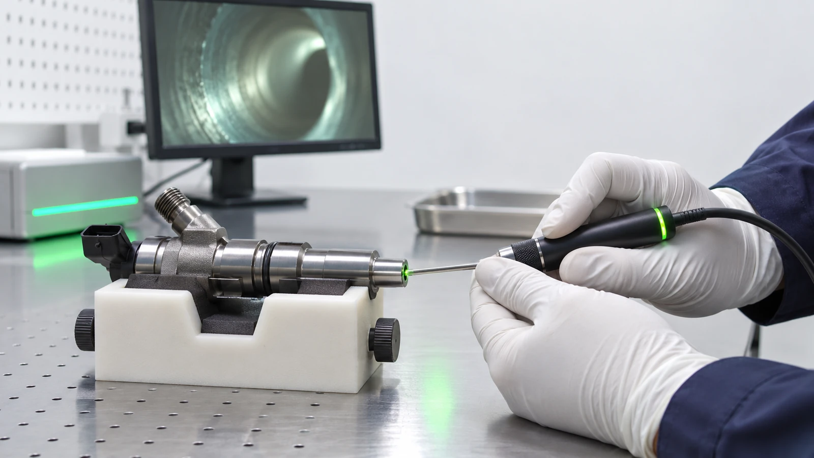
For a first article, agree on the inspection setup, datum simulation, sampling points, and report contents. For an internal channel, document how the inspection method detects the relevant condition. If the drawing requires a performance or flow test, define the test setup and acceptance criteria separately from dimensional inspection. A process claim is not a substitute for recorded evidence.
Trace the reported results to a part identifier, revision, material lot or certificate when required, operation state, and measurement setup. That context helps the engineering team distinguish a true part issue from a changed drawing or a different measurement routine.
A practical RFQ checklist
Send the current drawing and model, revision, material and condition, quantity, surface-treatment notes, critical features, and required inspection records. Identify the intended program stage: prototype fit check, design iteration, or a low-volume build. If the internal passages or edge condition are important, state how they should be verified rather than relying on a generic deburring note.
Ask the supplier to flag assumptions about stock form, setup count, finishing sequence, cleaning, and inspection access. If a dimension is difficult to measure after assembly or treatment, resolve the method before production. A drawing review for automotive prototype parts should connect the body’s critical features to the actual question the prototype must answer.
Once the scope is clear, a supplier can quote the specified part rather than a generic injector-shaped component. The most useful quote explains the planned process and the evidence it will return, while leaving approval of design changes and material substitutions with the customer.
Preguntas frecuentes
Is the fuel injector body the same as the fuel rail?
No. The rail distributes fuel to injectors; the injector body is an individual injector component. They can share a fuel-system context but have different geometry, manufacturing questions, and search intent.
Does a clean outside surface prove the internal passages are burr-free?
No. Internal intersections may be hidden from normal visual inspection. The drawing and agreed inspection plan should define how the relevant edge or passage condition is verified.
Can a prototype machining route represent a production injector process?
Only for the questions it was designed to answer. Material, blank, operation sequence, and volume can differ, so prototype results should not be presented as automatic production-process qualification.
What should an RFQ emphasize?
State the material condition, passage geometry, critical interfaces, post-treatment dimensions, cleaning requirements, and inspection evidence. These details help a supplier assess the whole part rather than quote only its visible turned surfaces.