- Start with the housing’s mechanical boundaries
- Choose datums before choosing setups
- Protect alignment across intersecting bores
- Manage thin walls, stock, and clamping forces
- Make sealing features inspectable
- Build an inspection plan around the reference frame
- What to include in a steering housing RFQ
- Frequently asked questions
Start with the housing’s mechanical boundaries
Before selecting tools, classify the housing features by function. A rack bore guides a moving member. A pinion bore and related geometry establish engagement with the rack. Seal grooves, end features, mounting pads, threaded holes, and any fluid passages complete the interfaces. The exact design varies, so the article’s terminology should be checked against the project drawing rather than inferred from a product photo. Separate component requirements from system-level requirements. A machined body can be inspected for dimensions, position, surface condition, and specified leakage behavior. It cannot, by itself, prove steering feel, vehicle response, durability, or safety. Those results depend on the complete assembly and validation plan. Keeping that boundary clear makes the RFQ more useful and prevents a supplier from guessing at acceptance criteria.
Choose datums before choosing setups
A common planning error is to select a convenient face as the first datum and only later discover that the assembly references another feature. The drawing should identify the functional axis, mounting plane, and any clocking or locating features. If the rack bore controls alignment, use it as a central reference in the inspection concept; if the assembly is located from mounting pads or a separate reference, state that relationship explicitly. Translate the datum scheme into machining steps. The blank may need a stable locating surface before the final bore is produced. A process plan might rough the main geometry, establish the mounting reference, semi-finish the bores, and complete critical interfaces after stock removal has stabilized. That sequence is not universal. It should be reviewed against the blank, wall thickness, clamping access, and the features that must remain aligned.
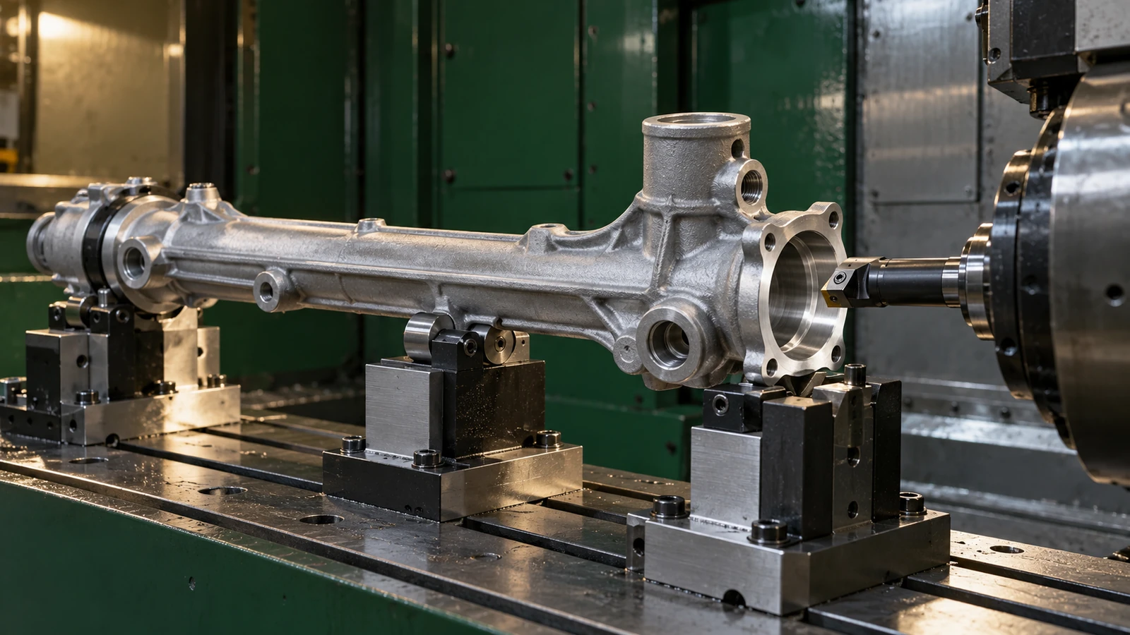
Protect alignment across intersecting bores
Rack and pinion bores may be perpendicular or otherwise related according to the design. Their relative position and orientation can affect assembly, contact, and the clearance available for seals or bearings. Specify the relevant position, orientation, size, and surface requirements on the drawing. Avoid replacing them with a vague “precision bore” note: it does not tell the machinist which axes must agree or the inspector how to report them. Tool access is part of the geometry review. Deep bores, intersecting passages, limited chip exit, and thin surrounding walls can constrain tool length, rigidity, and measurement access. The DFM review should identify whether a tool can reach the full feature and whether the inspection method can verify its location. If an internal feature cannot be measured directly, agree on an appropriate process-control or verification approach before production rather than assuming an outside dimension proves it.
Manage thin walls, stock, and clamping forces
Housing walls can move under cutting and clamping loads. Removing material unevenly may release stresses in a blank; clamping a flexible section too hard can make the part appear true while it is held and allow it to spring after release. A robust setup supports the part near the features being machined without distorting the geometry that will later be measured. Balanced roughing, a staged finishing sequence, and consistent support points are common planning tools, but the exact method depends on the material, blank, and shape. If a cast or forged blank is specified, review its allowance and condition before promising that every critical feature can be produced from the available stock. The automotive material-selection guide is a useful starting point for discussing material tradeoffs; the customer’s approved specification controls the actual grade and condition.
Make sealing features inspectable
Seal grooves, counterbores, thread seats, and mating faces should be specified with enough detail for both machining and inspection. Identify groove width, depth, corner treatment, surface condition, and the reference from which each is measured where those values matter. A seal groove can be dimensionally plausible yet fail to match the selected seal or assembly stack if the drawing omits the interface definition. If a housing contains fluid passages, ports, or plugs, define how each passage connects and which areas require deburring and cleaning. State whether a leak test is required, along with the test configuration and acceptance rule. Do not assume that a pressure or leak check proves all internal edges are free of burrs, or that a dimensional report proves passage cleanliness. Each inspection record answers a different question.
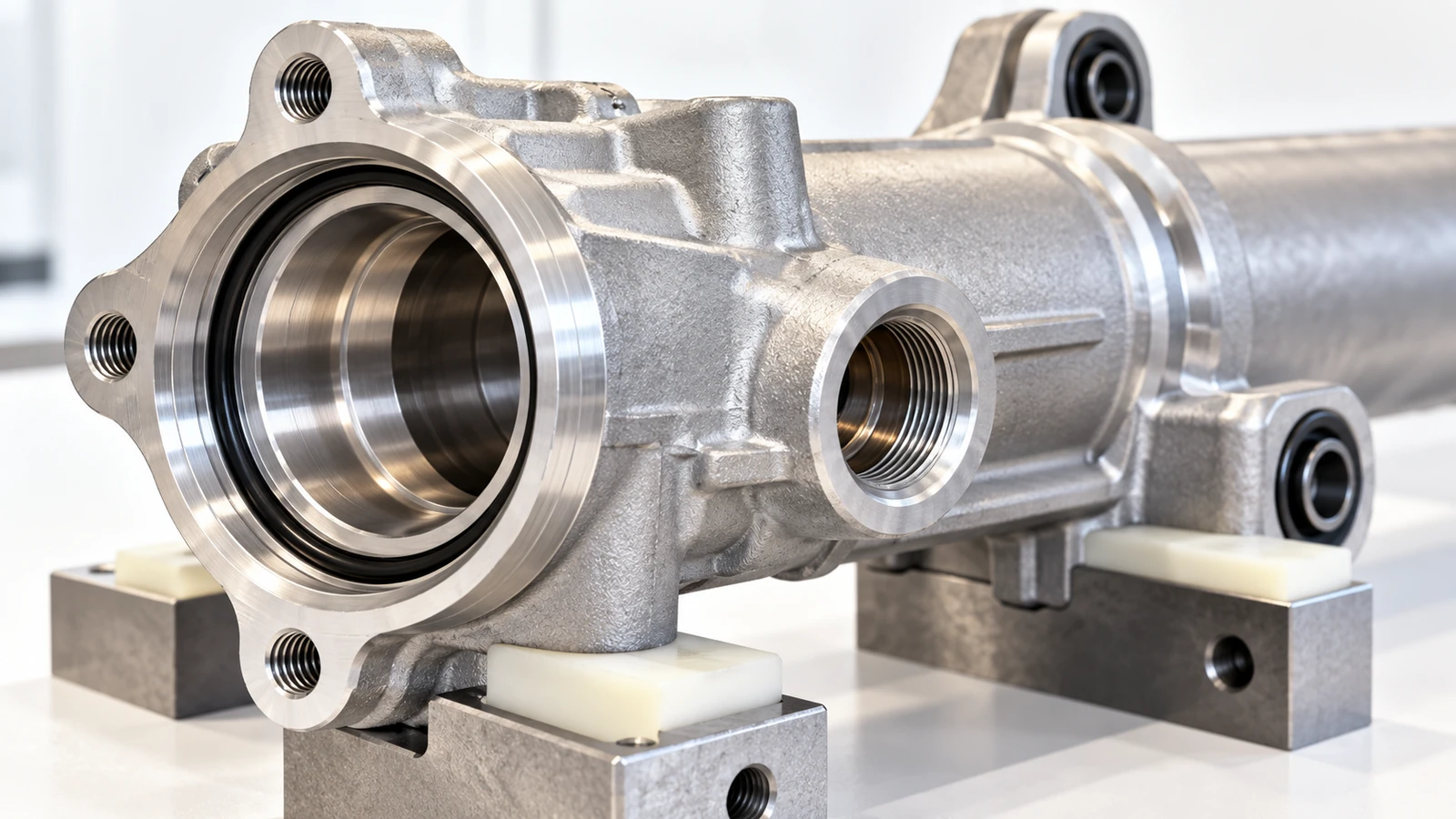
Build an inspection plan around the reference frame
Inspection should connect the main bore axes, mounting pads, port locations, and sealing surfaces in a repeatable coordinate system. For a prototype, the measurement setup might use a CMM or a suitable fixture, based on feature accessibility and drawing requirements. The report should identify the datum alignment and the measured features. When only selected dimensions are critical, identify them in the drawing or inspection plan so the supplier does not mistake a long list of nominal dimensions for a prioritized acceptance strategy. Inspect before and after finishing where the process can affect critical surfaces. Confirm whether the measurement is made on the bare machined part, after coating, or after any inserts or plugs are installed. Protect bores and seal lands during handling. If the design will change, retain revision control so results from one housing configuration are not attributed to another.
What to include in a steering housing RFQ
Provide the current 3D model, fully dimensioned drawing, material and condition, quantity, finishing requirements, sealing details, datum reference frame, and requested inspection records. Include mating-part information when a fit depends on a bearing, seal, rack, pinion, or mounting structure. Flag the build stage and identify which design inputs are still open. Ask for feedback on bore access, wall support, blank allowance, deburring, and test setup before the quotation is finalized. A focused manufacturing discussion is more valuable than a request to “hold tight tolerances everywhere.” The supplier can then spend effort on the features that govern the assembly while identifying risks that need a design decision.
Frequently asked questions
Which feature should be machined first?
There is no universal first feature. Establish the datum frame from the assembly drawing, then choose a sequence that creates stable references and preserves the bore relationships.
Does a machined housing prove steering performance?
No. Dimensional and specified functional checks apply to the component. Vehicle response and system performance require assembly-level validation defined by the design authority.
Should all internal passages receive a leak test?
Only where the design and acceptance plan require it. Define the ports, test condition, duration, medium, and acceptance criterion rather than relying on a generic note.