


Automotive Mechanical Subassemblies succeed when individually acceptable parts also work together without forcing, rework, uncertain adjustment, or hidden damage. The difficult work is controlling the interfaces between housings, brackets, shafts, covers, seals, fasteners, inserts, and electrical or thermal features. A subassembly is therefore a system of relationships, not merely a bag of finished components.
This guide explains how engineering and procurement teams can define those relationships, select coordinated manufacturing processes, and verify the assembled unit before a design moves into a larger production program.
Map the subassembly before quoting
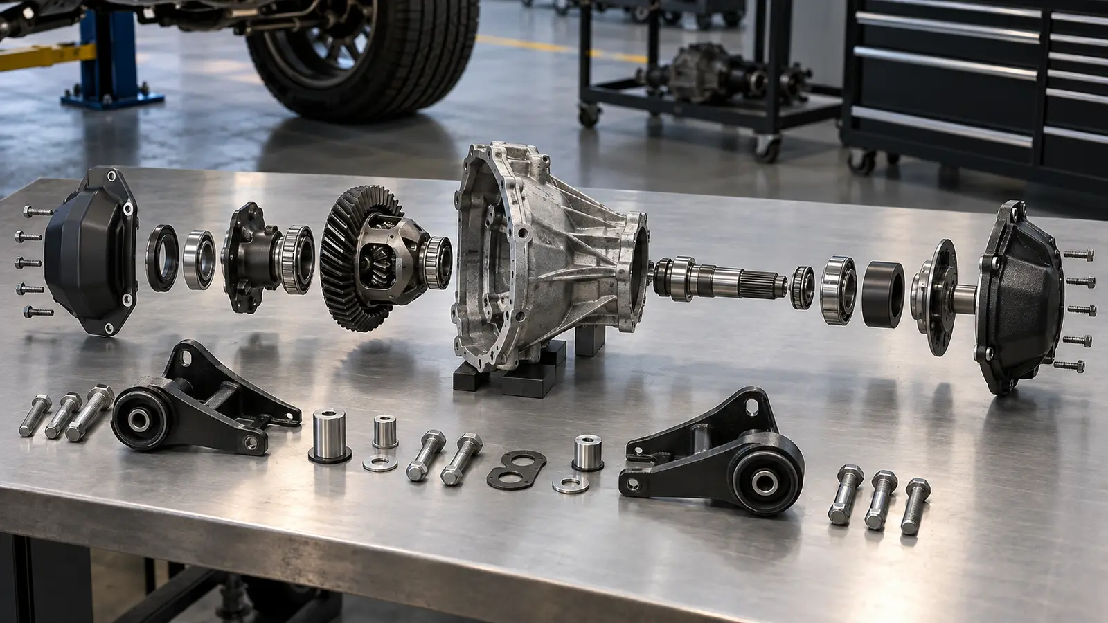
Start with the bill of materials and the complete assembly model. Identify every mating surface, locating feature, fastener, seal, moving interface, cable path, heat source, and service access requirement. Mark which dimensions control alignment and which are simply cosmetic. This map gives the manufacturer a clear view of the complete product rather than isolated part numbers.
For early vehicle development, automotive rapid prototyping allows the team to evaluate interfaces and installation behavior before a production route is fixed. The prototype should include enough surrounding geometry to expose clearance and tool-access problems.
Control interfaces, not just individual dimensions
| Interface | Primary control | Failure if missed |
|---|---|---|
| Locating feature | Datum and position tolerance | Misalignment |
| Fastener joint | Hole, torque, and access | Loose or inaccessible joint |
| Sliding or rotating fit | Clearance and finish | Binding or noise |
| Sealing surface | Flatness and compression | Leakage |
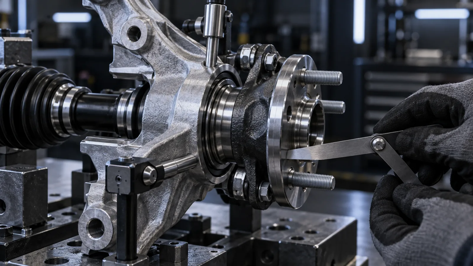
Tolerance stack-up should be calculated from the functional datum scheme. Do not simply add every drawing tolerance and call the result a system tolerance. Identify the actual chain between the locating feature and the final requirement. A supplier can then propose machining, molding, sheet metal forming, casting, or adjustment features that address the real risk.
Coordinate the manufacturing processes
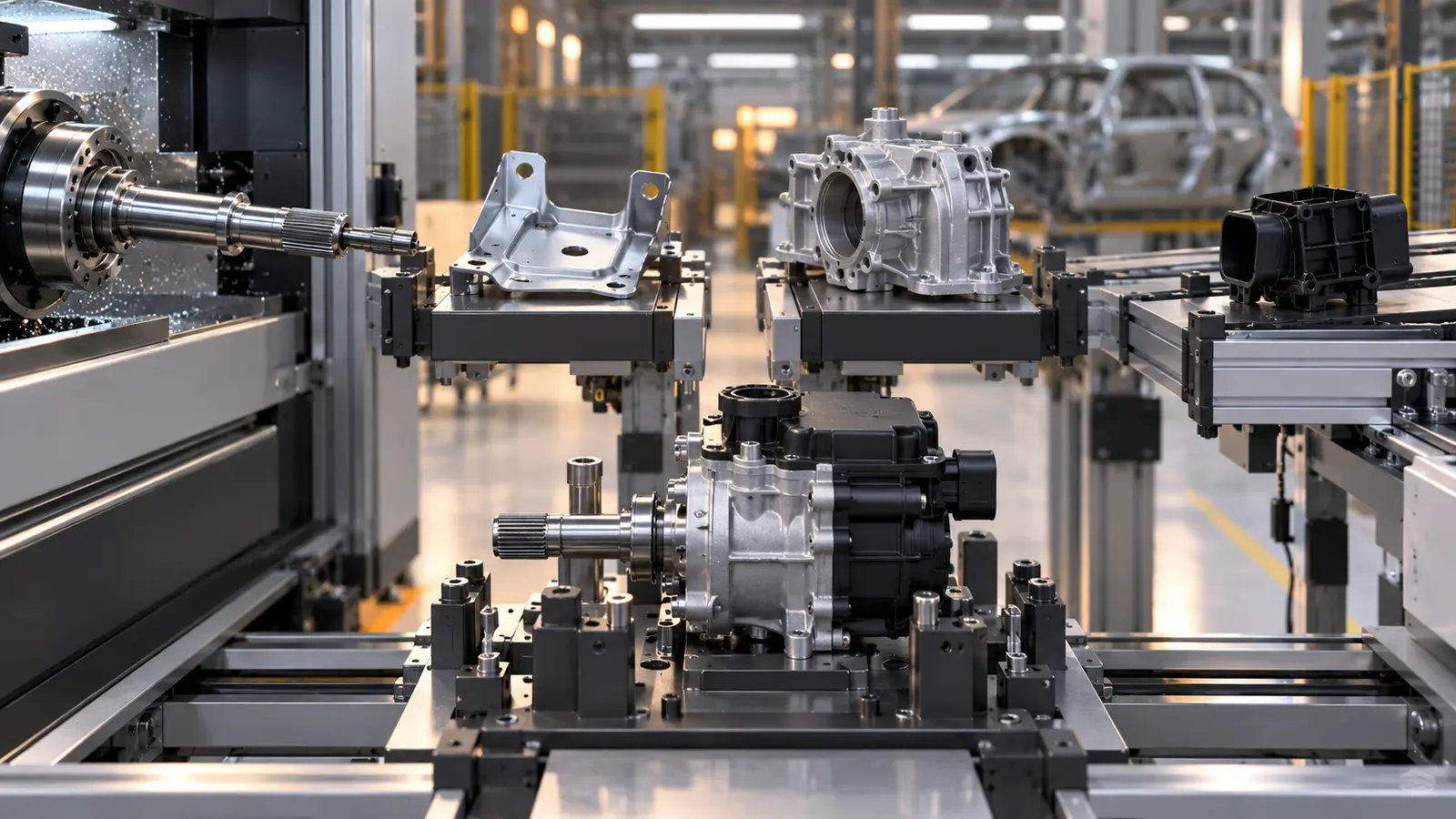
A subassembly may combine CNC-machined aluminum, injection-molded plastic, formed sheet metal, die-cast housings, printed prototypes, inserts, and finished surfaces. Each process creates a different variation pattern. Machining can establish accurate datums; molding introduces shrinkage and parting-line considerations; sheet metal adds bend allowance and springback; casting may require machining allowance and porosity review.
El CNC machining capability is especially relevant when a subassembly depends on accurate bores, mounting faces, threads, or alignment features. Those features should be defined before other suppliers build around them.
Finishing is part of the interface too. Coatings can change hole fit, grounding, friction, and sealing. If parts are painted, anodized, plated, blasted, or deburred, inspect the finished condition rather than accepting a pre-finish measurement as final proof.
Build the assembly sequence around access
- Establish the primary locating datum.
- Install inserts, seals, or hidden components while access remains open.
- Join the main parts using the specified torque or joining method.
- Route cables and verify clearance before closing the enclosure.
- Perform the functional and dimensional checks that depend on assembly.
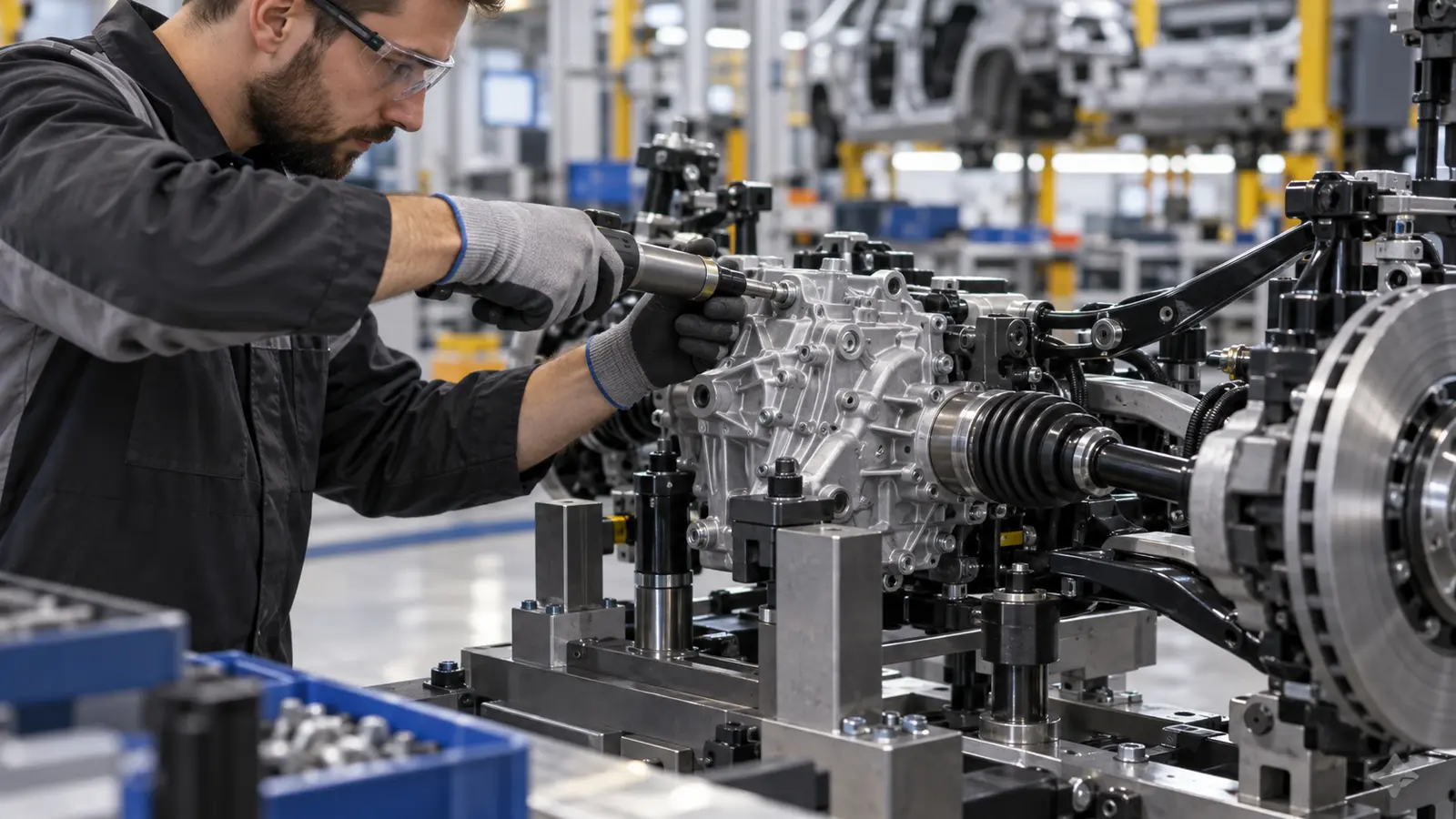
Tool access, operator reach, adhesive cure time, seal compression, and the order in which components become inaccessible can all change the correct sequence. A design review should therefore include the person who will build or service the unit, not only the person who created the CAD model.
Verify the completed unit
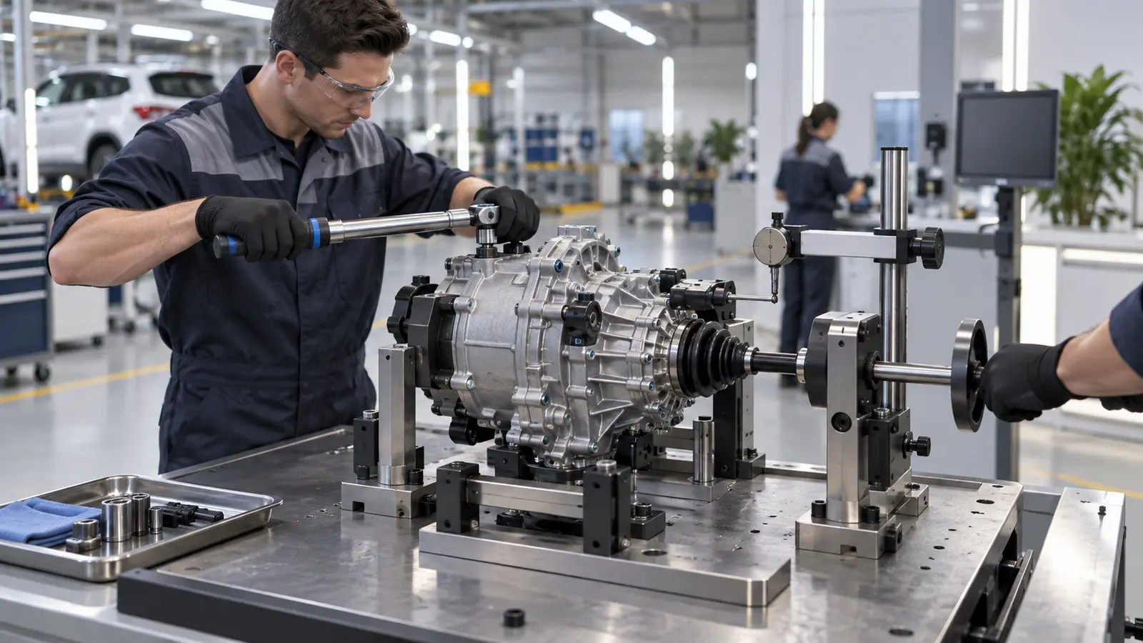
Inspect loose parts first, then repeat the critical checks after assembly. Measure gap, flushness, movement, torque, leakage, electrical continuity, vibration response, or load transfer according to the function. If a feature is hidden after assembly, define an earlier checkpoint or a suitable indirect test.
Separate temporary adjustment from true process capability. If an operator files a hole, adds a shim, or changes torque to make a unit work, record that action as evidence of a design or process issue. The goal is a repeatable assembly, not a single successful build.
Prepare an RFQ that shows the whole system

Include the BOM, 3D models, 2D drawings, mating interfaces, datum scheme, quantities, assembly sequence, finish requirements, inspection plan, packaging needs, and functional tests. Explain which parts must be supplied together and which can be sourced separately. Ask the manufacturer to identify tolerance risks, recommended process splits, and inspection points before quotation.
A coordinated manufacturing partner can reduce handoff errors by reviewing the complete route from prototype parts to low-volume production and final assembly. That review is especially useful when the subassembly combines several materials and processes.
Frequently Asked Questions

Why can a subassembly fail when every part passes inspection?
Interface stack-up, datum mismatch, joining distortion, coating thickness, or assembly access can create a system-level failure even when individual parts meet their drawings.
Should one supplier make every component?
Not always. However, coordinated design review and assembly ownership can reduce variation between suppliers and make responsibility clearer.
When should assembly testing begin?
Begin as soon as the critical interfaces are defined. Early testing exposes access, stack-up, and sequence problems before they become tooling changes.
What is the most important information in an RFQ?
The complete assembly model, functional requirements, critical datums, quantity, material, finish, inspection method, and intended assembly sequence.

