


Define the manufacturing scope
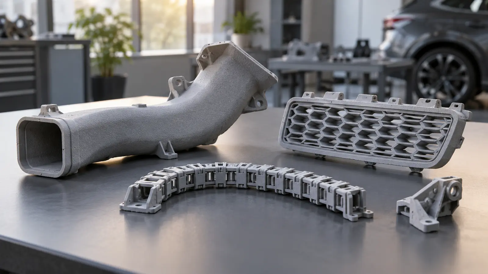
Start with the vehicle function, critical interfaces, expected quantity, exposure, and test conditions. A prototype, pilot part, and production component may need different materials and process controls.
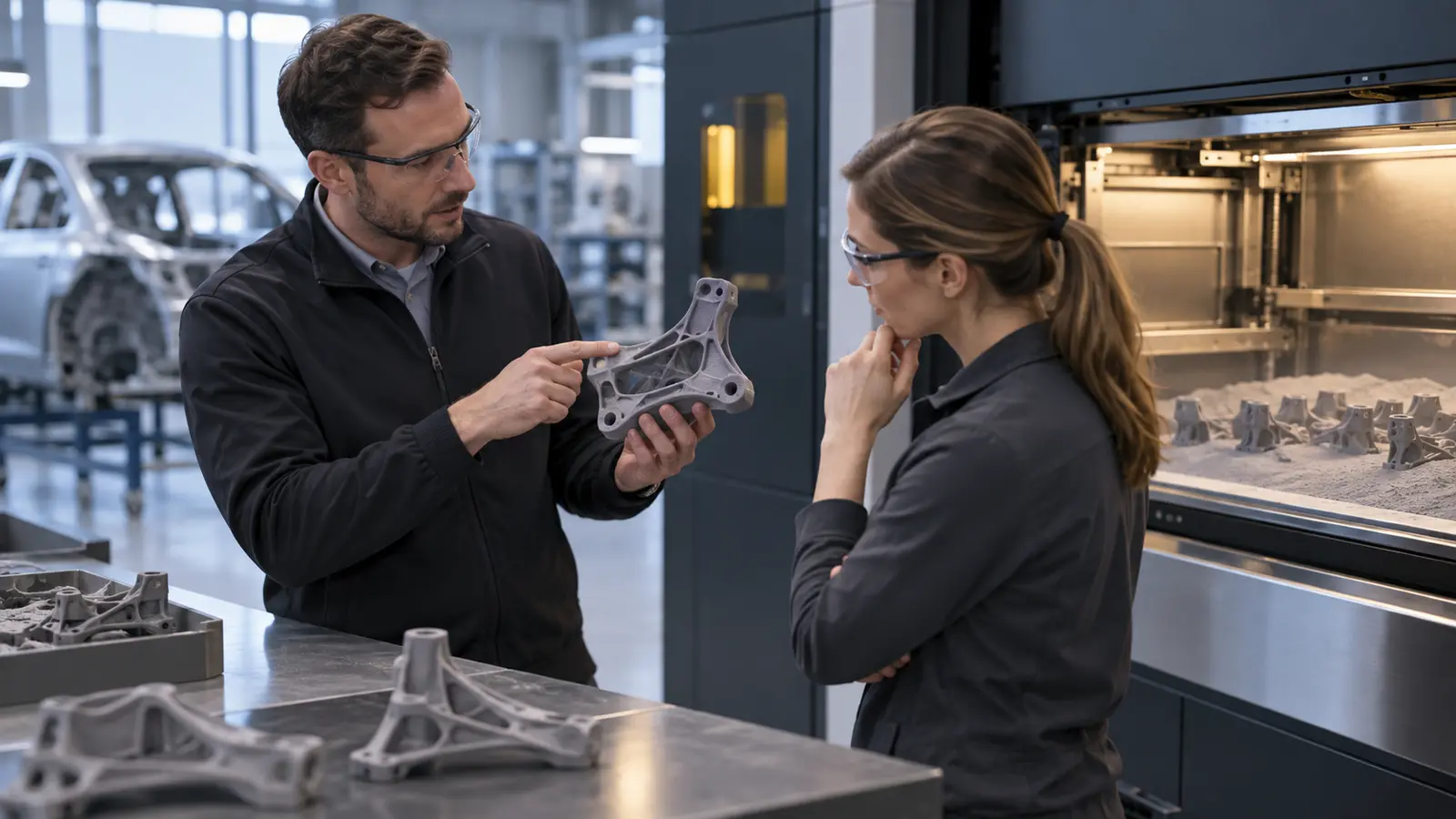
Nuestro automotive rapid prototyping workflow connects geometry, material, and assembly decisions early.
Design around the process
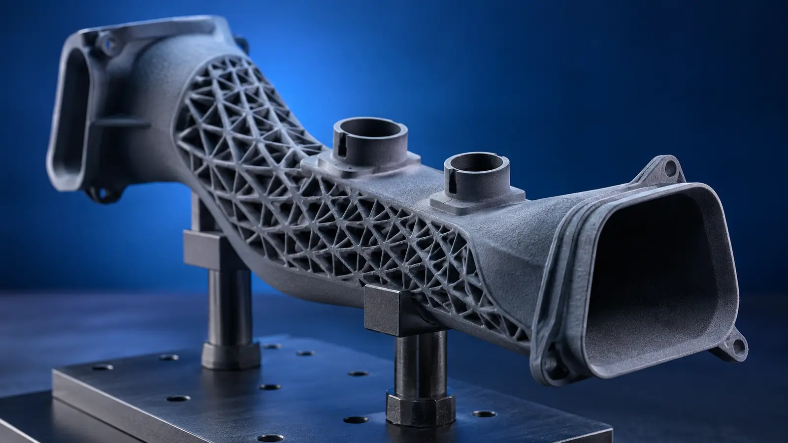
Review wall transitions, datums, access, joining, surface requirements, and likely secondary operations before release. Manufacturing constraints should be visible in the drawing rather than discovered after sampling.
| Requisito | Review point |
|---|---|
| Fit | Datums and interface stack-up |
| Función | Load, temperature, and movement |
| Apariencia | Texture, finish, and visible zones |
| Quantity | Tooling and repeatability |
Connect production with inspection
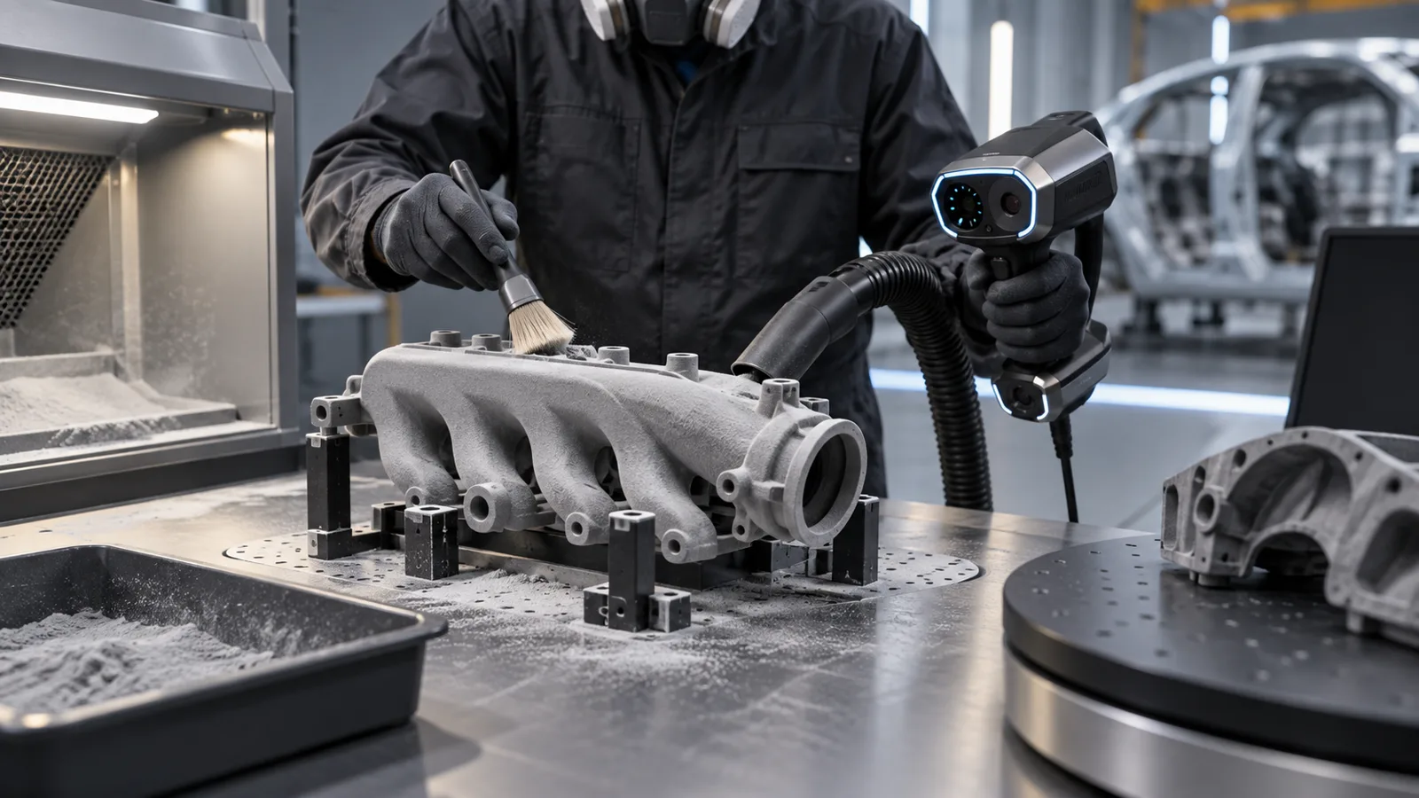
Define first-article checks, critical dimensions, material records, finish verification, and assembly tests. Inspect the completed part or subassembly when the requirement depends on the relationship between several features.
Use the relevant surface finishing services and process route together so finishing does not change a critical fit.
Choose the next step from evidence
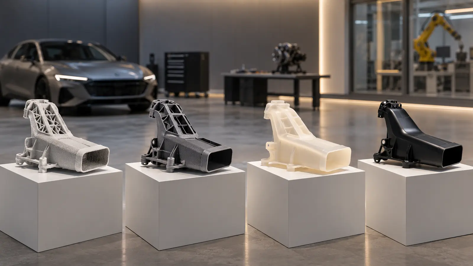
Compare prototype results with the intended production requirement. Record what is representative, what remains provisional, and which design or process change should happen next. This turns a single batch into useful program knowledge.
Frequently Asked Questions
What should determine the process?
Function, quantity, geometry, material, finish, tolerance, and validation conditions.
Why is inspection planned early?
Because a requirement that cannot be measured or located clearly is difficult to control.
Can several manufacturing processes be combined?
Yes. CNC, molding, sheet metal, additive, casting, finishing, and assembly can be combined when each solves a defined part of the program.
A closer engineering review of automotive SLS 3D printing
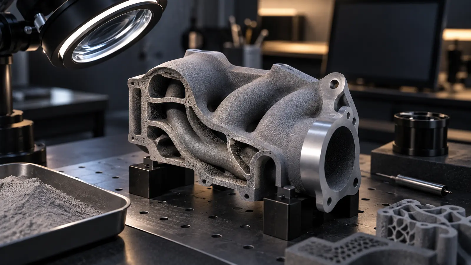
The manufacturing route should be selected from the function of the automotive part, the quantity required, and the evidence the development team needs. A prototype used only for packaging can tolerate different material and surface variation from a part used in a temperature, vibration, torque, or sealing test. Defining that difference at the beginning prevents a visually convincing sample from being interpreted as production-equivalent evidence.
Start with the interfaces. Identify mounting faces, locating holes, clips, seals, fasteners, connectors, moving surfaces, and areas that operators or service technicians must reach. Then mark the critical datums and calculate the tolerance chain between the part and its mating components. This is where many automotive prototypes fail: the individual part is acceptable, but the assembled relationship is not.
Material selection should follow the environment. Consider stiffness, impact resistance, thermal expansion, chemical exposure, moisture, abrasion, electrical requirements, and appearance. If the prototype material differs from the production material, record the difference in the test plan. A material name alone does not define performance; grade, process, orientation, finish, and exposure history can all affect the result.
Design for manufacturing also includes secondary operations. Review trimming, drilling, tapping, machining, deburring, cleaning, coating, painting, assembly, and inspection before the first order. These operations can change dimensions and surface behavior. Critical features should be inspected after the final operation that can affect them, not only after the primary manufacturing step.
| Decision | Information to provide | Useful output |
|---|---|---|
| Proceso | Geometry, quantity, material target | DFM review |
| Calidad | Critical features and acceptance | Inspection plan |
| Validation | Load and exposure conditions | Test report |
| Handoff | Revision and traceability needs | Production learning |
A good supplier review should explain what can vary, how it will be measured, and which features require special handling. Ask for assumptions about orientation, support, gate or flow behavior, insert location, tool access, finishing, and packaging where relevant to automotive SLS 3D printing. The purpose is not to demand unsupported numbers. It is to make every important assumption visible before parts are made.
Testing should reproduce the real use condition as closely as the prototype purpose allows. Check installation cycles, torque, movement, temperature, vibration, moisture, chemical contact, and service access as appropriate. Photograph failures, record measurements, and connect each result to a design feature or process step. A failed prototype is useful when it narrows the next decision.
For low-volume programs, flexibility is valuable because the model may change. That flexibility should still be controlled through revision numbers, approved material records, first-article checks, and a clear distinction between cosmetic samples and functional samples. When the design stabilizes, compare the prototype route with the intended production process and document which properties need to be revalidated.
An RFQ should include the CAD model, drawing, quantity, material preference, finish, mating components, critical datums, test objective, inspection method, packaging requirements, and delivery stages. Include photographs or marked-up views when a surface, interface, or assembly action is difficult to understand from the model. Clear input reduces avoidable clarification cycles and makes the quote more useful to engineering.
How should the first sample be judged?
Judge it against the stated validation question, the approved drawing, and the declared material and process limitations. Do not use a visual pass as evidence of strength, thermal performance, or long-term durability unless those properties were actually tested.

