


A turbopump housing is not simply a thick shell around a rotating assembly. It establishes the position of bearing supports, seals, fluid passages, and mounting interfaces while containing a demanding operating environment. That combination makes the manufacturing sequence part of the design: a passage that is easy to machine may leave too little stock around a sealing land, while a convenient datum may not control the alignment that assembly actually depends on.
For a development team, the useful question is not only whether a supplier can cut the shape. It is whether the drawing, material condition, machining plan, inspection strategy, and change history describe the same part. This guide focuses on those decisions for prototype and low-volume aerospace manufacturing and prototyping, without assuming that a machined prototype is automatically flight-qualified hardware.
Contents
- Start with interfaces, not the outer envelope
- Separate passage geometry from machine access
- Plan the machining route around datums
- Choose material by temperature, fluid, and program stage
- Make inspection reflect assembly risk
- Use prototypes to resolve the right unknowns
- Control revisions through the supplier handoff
- Questions teams should settle before release
Start with interfaces, not the outer envelope
Begin by marking every interface that positions, seals, supports, or connects the housing. Typical examples include bearing bores, shaft-related clearances, cover faces, ports, fastener patterns, locating features, and surfaces that contact adjacent components. Not all surfaces deserve the same inspection effort. A cosmetic outside wall and a bore that locates a rotating element have very different consequences if they move during machining.
Translate the assembly drawing into a short interface map. For each critical feature, record its mating part, functional role, datum relationship, and verification method. This brings hidden assumptions to the surface: perhaps a port pattern is dimensioned from the casting envelope even though assembly locates from a machined face, or perhaps a sealing surface is controlled in a separate view without a clear relationship to the bore axis.
Define the intended prototype use as well. A geometry model used for packaging may tolerate a different material and finish from a fit-check unit or a test article. If the part will see pressure, hot fluid, vibration, or high rotational loads, the responsible engineering authority must define the applicable design and qualification requirements. A prototype machining supplier can manufacture to released specifications; it cannot infer or certify an unstated qualification basis.
Separate passage geometry from machine access
Internal flow paths often dominate the housing design, but their manufacturing implications vary. Straight drilled passages, intersecting cross-holes, milled channels closed by a cover, and cast or additively formed cavities each create different access, cleaning, and inspection questions. A CAD model can show a continuous passage without showing how a cutter reaches it or how chips and burrs will be removed afterward.
Review each passage with four checks: tool approach, remaining wall thickness, intersection condition, and post-process access. If two bores meet at an angle, the breakthrough can create a sharp internal edge or an unreachable burr. A plug may solve access but introduces another sealing interface and a new inspection item. A milled channel with a bolted cover may simplify machining while increasing the number of joints. Those are design tradeoffs, not merely programming details.
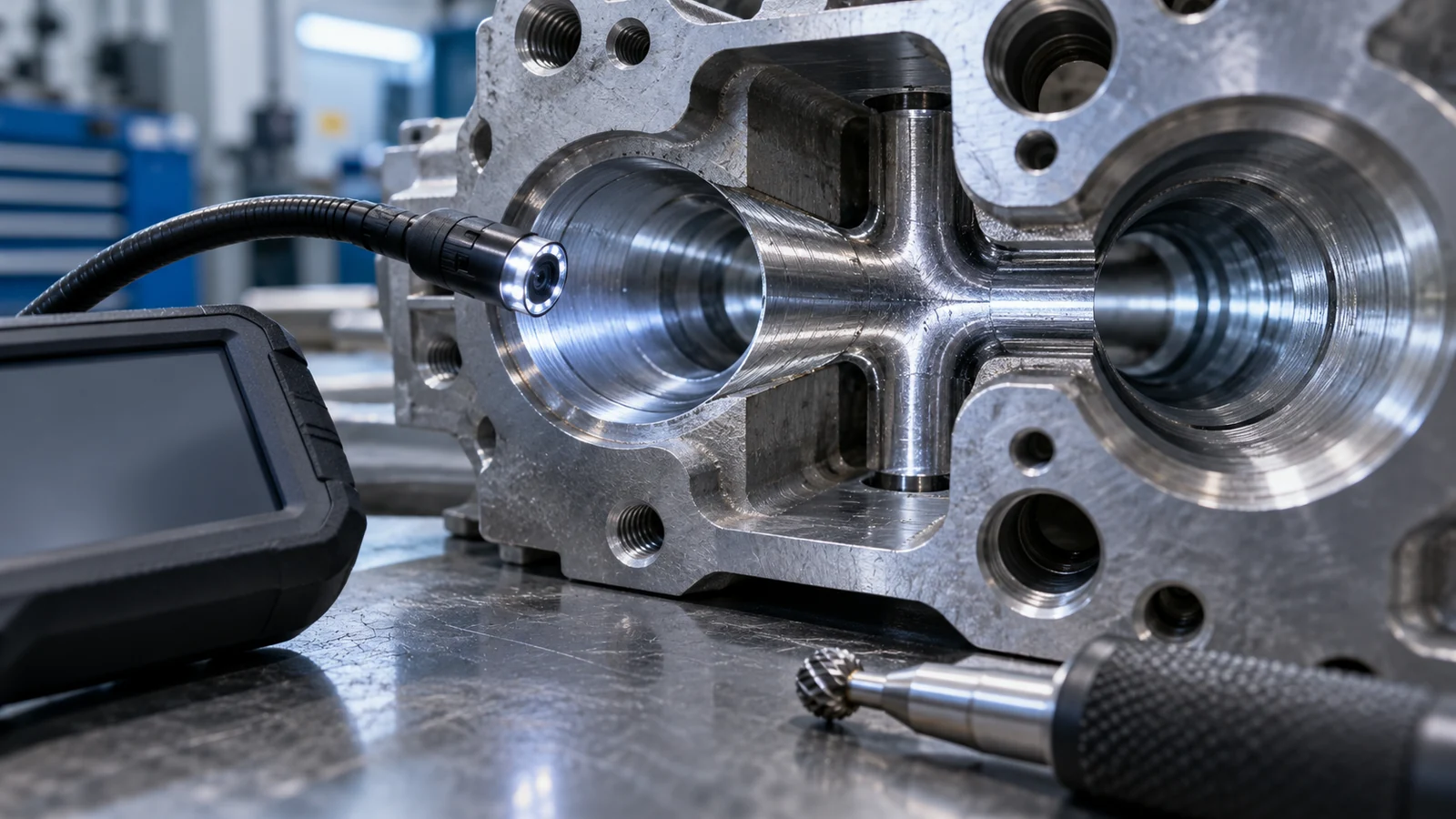
Where the drawing permits, use generous internal radii, consistent tool-access directions, and clearly defined edge conditions. Avoid specifying a finish or tolerance on hidden surfaces unless it serves a function and can be verified. For each inaccessible feature, agree on an evidence method鈥攕uch as borescope review, flow check, validated cleaning process, or another engineering-approved method鈥攂efore the part is made. The appropriate method depends on the actual requirement and must not be substituted by visual assumption.
Plan the machining route around datums
A robust route usually starts with stock preparation and a stable reference, then establishes the interfaces that control the part in assembly. Roughing may remove substantial material and release residual stress, so a plan that finishes every critical face in one uninterrupted setup is not always realistic. The route should identify when the part is rough-machined, when it is allowed to stabilize if needed, and when final datum features are cut.
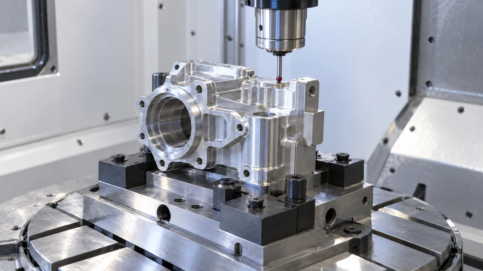
For a housing with several intersecting bores, the key decision is how to preserve their relationship across setups. A fixture may reference a machined mounting face and locating features; probing or coordinate measurement can then verify the setup before the next operation. If a feature is moved to a new setup, the drawing鈥檚 datum scheme should still explain how the resulting position is evaluated. This is where a practical aerospace manufacturing process plan connects product intent to actual machining and inspection steps.
Do not treat five-axis access as a universal fix. Multi-axis machining can reduce repositioning for complex geometry, but setup stiffness, cutter reach, chip evacuation, and feature accessibility still matter. Conversely, splitting a part into two pieces may ease machining but add joints, fasteners, and leakage paths. Compare the complete part route鈥攊ncluding deburring, cleaning, inspection, and assembly鈥攏ot only cycle time at the machine.
Choose material by temperature, fluid, and program stage
Material selection should follow the operating envelope and the purpose of the build. Consider temperature, pressure, fluid compatibility, strength, stiffness, thermal growth, corrosion exposure, mass, and downstream joining or coating. A material chosen for an inexpensive geometry check may not represent the behavior of a later test unit. Mark that distinction on the drawing and in the purchase documentation so a visually similar prototype is not mistaken for a representative article.
| Decision factor | Why it matters to the housing | What to define |
|---|---|---|
| Operating environment | Heat, fluid, and pressure can affect material suitability and sealing | Temperature range, media, pressure basis, and applicable design authority |
| Structural interfaces | Bores, mounts, and covers carry loads and locate the assembly | Critical dimensions, datum scheme, and inspection evidence |
| Prototype purpose | Packaging, fit-check, and functional testing require different representativeness | Use case, material condition, and limitations |
| Manufacturing route | Stock form, wall sections, and access influence distortion and cost | Blank form, machining sequence, finishing, and cleaning needs |
For machined development parts, aluminum, stainless steel, and titanium alloys may appear in different program contexts, but no alloy family is automatically appropriate for every turbopump location. Confirm the exact grade, condition, product form, and required records with the design authority. The site鈥檚 aerospace materials overview can help frame that conversation; it does not replace application-specific material approval.
Make inspection reflect assembly risk
Inspection planning is strongest when it begins with the interfaces and risks identified earlier. A useful plan pairs each controlled feature with a characteristic, method, acceptance source, and record. Bore size may be checked with an appropriate instrument; position and orientation may require coordinate measurement; a sealing face may need a specified flatness or surface condition. The exact instrument and acceptance limit must come from the drawing or approved plan, not from a generic article.
Separate in-process checks from final acceptance. In-process measurement can detect a setup shift before more material is removed, while final inspection documents the released part state. If a passage is hidden after plugging or assembly, inspection evidence should be collected before closure. Include deburring and cleanliness requirements where they are functional; a dimensionally conforming housing can still cause trouble if a loose chip, burr, or residue remains in a fluid path.
For a low-volume build, establish how nonconformances and drawing questions are handled. A supplier should identify the affected feature, hold the part when needed, and obtain an approved disposition rather than silently blending or reworking a critical surface. This keeps inspection records useful for engineering decisions instead of reducing them to a pass/fail sheet detached from the design intent.
Use prototypes to resolve the right unknowns
Prototype value comes from a deliberate test question. A first build may answer whether the tool can reach a passage, whether a fixture is stable, whether the housing clears neighboring hardware, or whether the proposed datum scheme produces measurable results. Write down the question before release and connect it to the drawing revision, material, and inspection record.
When geometry is still changing, a staged approach can reduce wasted effort. A machined blank or simplified model may answer packaging questions; a more representative build can then validate interfaces and inspection access. Rapid prototyping is useful only when its process and material limitations match the question. Polymer or additive models can reveal envelope conflicts, but they do not demonstrate metallic stiffness, sealing, pressure capability, or thermal performance.
Keep each iteration comparable. If a bore location changes, record whether the fixture, measurement method, and mating reference stayed the same. If they changed too, apparent improvement may be caused by the measurement setup rather than the design revision. This discipline makes prototype results more transferable to the next manufacturing stage.
Control revisions through the supplier handoff
A complete release package should include the current drawing and model, revision identifiers, material and condition, critical characteristics, surface and edge requirements, inspection expectations, and any approved departures. State which document governs when a model and drawing disagree. Include a clear change log for revised ports, bores, interfaces, or wall sections; otherwise a supplier may quote or machine from a stale file.
Before production begins, review manufacturability questions together: which features are difficult to access, which datums will locate each setup, where inspection occurs, and what evidence accompanies delivery. Early clarification is particularly valuable for complex housings because small geometry changes can alter tool access, stock allowance, and inspection strategy at once.
The central lesson is straightforward: a turbopump housing is a coordinated set of interfaces and passages, not just a contoured block. When function, geometry, material, route, inspection, and revision control are aligned, a prototype can answer useful engineering questions and create a cleaner path to later builds鈥攚ithout overstating what the prototype proves.
Questions teams should settle before release
Can a machined prototype prove the final housing is qualified?
No. It can confirm only the characteristics and tests defined for that prototype. Qualification requires the applicable program requirements, approved procedures, and responsible engineering authority.
Should every internal passage receive a surface-finish tolerance?
Only where the finish is tied to function or a verifiable requirement. Unnecessary limits can add cost without improving performance, while inaccessible features may be difficult to inspect after manufacture.
When should the supplier review the model?
Before quoting or releasing the machining plan, especially when passages intersect, walls are thin, or critical interfaces span multiple setups. Early review can expose access and datum issues while the design is still easier to change.

