


A transmission valve body can look like a compact aluminum block, yet its internal passages and spool bores help route hydraulic pressure to clutches and other transmission elements. It may match its outside dimensions and still create assembly or functional risk if bore axes, port locations, surface condition, or cleanliness drift from the approved drawing. That is why automotive transmission valve body machining should be planned as a coordinated geometry, process-sequence, and verification task, not as a list of holes to drill.
This guide focuses on manufacturing decisions a product engineer or sourcing team can review before requesting prototypes or a production quote. The drawing, material specification, and acceptance criteria remain the authority for each design.
Contents
- Read the hydraulic map before programming toolpaths
- Turn functional relationships into stable datums
- Choose a starting form that fits the development stage
- Sequence machining around distortion and access
- Keep burrs and chips out of the circuit
- Build an inspection plan around function
- Prepare a useful RFQ package
Read the hydraulic map before programming toolpaths
The first useful question is not “How many holes are there?” It is “Which surfaces and passages control the intended flow path?” A valve body may contain intersecting galleries, spool bores, threaded ports, sealing lands, mounting faces, and interfaces for plates or solenoids. Their importance is not equal. A datum face may locate the assembly, while a bore axis establishes the path a spool must follow. A cross-drilled passage may only work as intended if its position, intersection, and edge condition are controlled.
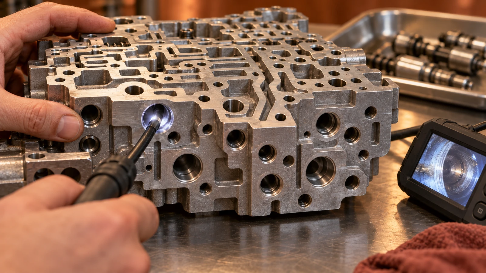
Separate functional features from convenient geometry. Mark the primary locating face, the bore axes that govern motion, sealing surfaces, and ports that connect to the hydraulic circuit. Then check which dimensions are basic, which have tolerances, and which geometric relationships are explicitly called out. A crowded drawing is not permission to infer a tighter requirement; unresolved requirements should go back to the design owner.
This review helps identify tool access. Long intersecting passages, deep bores, and ports close to thin walls can affect drill selection, setup direction, chip evacuation, and deburring access. If a feature cannot be reached or measured in the proposed setup, the process plan should address that before the first part is cut.
Turn functional relationships into stable datums
Valve-body machining is sensitive to relationships between features. A spool bore may be individually within size but still sit incorrectly relative to a mating plate, neighboring bore, or port pattern. The manufacturing plan should make the drawing’s datum scheme operational: which face locates first, how the part is restrained, and which subsequent operations preserve the same coordinate relationship.
For a prototype, engineers often need to learn whether the design can be made and assembled before optimizing a high-volume cycle. Stable fixture references can be more valuable than a one-off arrangement that makes the sample difficult to inspect or reproduce. If faces are machined in separate setups, explain how references transfer and how their relationship is verified.
Coordinate the machining sequence with the inspection method. A CMM can evaluate position and orientation when the drawing defines them, while bore gauges may suit specified diameters. The instrument does not decide what “good” means; the drawing and agreed inspection plan do. For context on the route itself, see the site’s CNC machining capabilities.
Choose a starting form that fits the development stage
The starting form changes both economics and risk. A machined billet can make sense for early iterations, limited quantities, or geometry that is still changing. A cast blank may become more attractive when the shape and production plan are stable enough to justify tooling. Neither route guarantees a better finished valve body: the stock must provide suitable machining allowance, access, and material condition for controlled features.
When evaluating casting, discuss parting lines, draft, local wall thickness, and stock on sealing faces and bores before tooling is released. A casting that saves material but leaves inadequate stock at a critical surface may be difficult to finish consistently. The site’s die-casting service is one possible upstream route; the alloy and casting specification remain project-specific.
Choose material from the application specification, not a generic “best alloy” claim. Review strength, temperature, fluid compatibility, corrosion environment, and joining interfaces with the design authority. For aluminum projects, the CNC aluminum material page is a starting point, not a substitute for a grade-and-temper requirement.
Sequence machining around distortion and access
A practical route may establish reference faces, rough the major cavities and bores, allow the part to stabilize if required, and then finish the features whose relationships matter most. The exact order depends on the part, blank, clamping, and drawing. Avoid finishing a datum early and then allowing later stock removal or clamping to shift it without a verification step.
| Stage | Planning question | Evidence to retain |
|---|---|---|
| Reference preparation | Which faces establish the coordinate system? | Setup sheet and datum identification |
| Roughing | Where could stock removal reduce stiffness? | Operation sequence and part condition |
| Critical finishing | Which bores, lands, and ports share a relationship? | Measurements required by the plan |
| Final verification | Can acceptance features be measured reliably? | Inspection record tied to drawing revision |
Tool reach and clamping also deserve a design-for-manufacture review. A change to a nonfunctional relief, tool approach, or fixture contact may improve access, but only the product owner can approve a design change. Keep proposals separate from the controlled model so the supplier does not machine an unapproved interpretation.
Keep burrs and chips out of the circuit
Intersecting drilled passages create edges that may be difficult to see externally. A burr can affect assembly, obstruct a passage, or detach during service; chips and residues can undermine downstream cleaning. These are reasons to define deburring and cleanliness controls, not to claim that one universal process guarantees hydraulic performance.
Identify cross-hole intersections and internal edges where they matter. Agree how those locations will be reached, what process evidence is expected, and how cleaning will be verified. If a passage is inaccessible to direct inspection, discuss a suitable method with design and quality teams before production. Avoid imposing a blanket finish value on every internal feature unless the specification supports it.
Cleaning belongs in the route. Part orientation, flushing direction, blind passages, protective packaging, and handling can affect whether residue remains or is reintroduced. Record the agreed acceptance criteria and keep the method consistent with the project’s material and fluid requirements.
Build an inspection plan around function
Inspection should answer whether controlled features meet the drawing, not merely produce a long report. Identify critical dimensions, datums, geometric tolerances, threads, sealing surfaces, and port locations. Match each requirement to an instrument and record the revision, method, and acceptance rule. A CMM report alone does not verify passage cleanliness or flow behavior.

Where function depends on a passage or sealing interface, the customer may specify a flow, leak, or pressure test. Such tests need agreed fixtures, limits, and conditions; they should not be invented by the machining supplier. A responsibility matrix prevents each party from assuming the other owns validation.
For a first article, compare manufactured features with the released design and resolve deviations through formal approval. Repeat orders benefit from preserving accepted setup references, inspection methods, and revision history. This creates traceability without implying that one prototype result establishes production capability.
Prepare a useful RFQ package
A useful inquiry includes the current drawing and 3D model, material and condition, prototype and repeat quantities, critical features, finish requirements, cleaning expectations, inspection records, and required functional tests. Flag undefined features. If the design is still changing, say so; that may favor a flexible prototype route over premature production tooling.
Jucheng can review the part around drawing-defined geometry, material, process route, and verification needs. The buyer benefits from a discussion connecting machining access and inspection to functional interfaces, rather than a quote based only on envelope size. Final tolerances, material approvals, and acceptance criteria remain controlled by the customer’s engineering documents.
Frequently asked questions
Can a valve body be machined from billet for a prototype?
It can be considered when geometry, quantity, and schedule suit a machined blank. Compare stock use, feature access, material requirements, and the learning expected from the prototype before choosing the route.
Should every spool bore receive the same tolerance?
No universal tolerance should be assumed. The drawing should define the size and geometric relationships needed for each function. Resolve missing requirements with the design authority rather than tightening dimensions by guesswork.
What should buyers ask about internal passages?
Ask how cross-hole burrs, chip removal, cleaning, inspection access, and specified functional tests are handled. Agree on acceptance evidence before ordering so it becomes part of the process plan.

