


A CV joint cage needs more than evenly spaced openings. Its windows, spherical surfaces, section thickness, and finished edges work within a specific joint assembly. A cage that accepts the balls while resting on a bench may still behave differently when the joint articulates. The manufacturing problem is to preserve the specified relationships through material processing, machining, and final inspection.
For prototype development, begin by identifying the joint design and the question the sample will answer. A geometry study, an assembly check, and an operating durability program require different evidence. This guide addresses component definition and process planning; it does not supply universal running clearances, heat-treatment recipes, or a vehicle-service approval.
Treat the windows and spherical surfaces as one geometry
A CV joint cage is part of an assembly that includes balls and mating joint members. Define those components and the model revisions used during development. Window width alone does not describe the ball contact. Window position, end geometry, local radii, and their relationship to the cage’s spherical surfaces can all matter to the intended motion.
Start with sections that show the actual contact and clearance regions. Identify the relevant sphere centers, axes, and window pattern. A circular silhouette in a rendered model can conceal a profile error or an inconsistent section. The drawing should make clear which surfaces guide the cage and which surfaces interact with the balls in the selected joint design.
Keep the angular range visible during review. A static assembly at the neutral position can hide contact that occurs at articulation. The design team should define the motion envelope and acceptance conditions. A supplier can then check tool access and inspectable geometry against that definition instead of guessing a clearance from the ball diameter.
Choose a prototype route for the question being asked
Machining from stock can provide flexibility when a design is changing or a small sample quantity is required. Forming or another near-net route may deserve consideration as the production design and volume become clearer. These routes create different starting geometry, material history, allowances, and tooling commitments. A prototype route should be chosen deliberately rather than presented as the inevitable production method.
For a cut prototype, compare the access needed to create the windows and spherical surfaces. Tool reach, interrupted cutting, clamping support, and the remaining wall can affect the plan. Machining a window also changes the stiffness of the blank. A process that holds a solid ring securely may need a different support strategy after several openings are created.
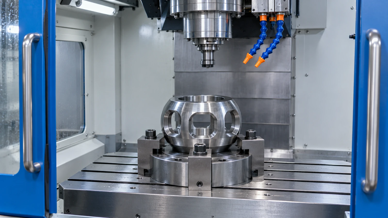
For a near-net blank, define the features left for finishing and the references used to locate it. An approximate spherical shape is not a finished guiding surface. Establish where variation can remain, which surfaces need machining allowance, and how the blank will be evaluated before expensive downstream operations. A lower stock-removal volume does not automatically mean a simpler acceptance process.
Put the material condition on the process map
The approved material and treatment depend on the joint requirements. Published suppliers list different steels and processing approaches; that does not establish interchangeability for a custom cage. Use the controlled specification and distinguish incoming stock condition from the final delivered condition. A general phrase such as “hardened steel” leaves important questions unanswered.
If treatment follows rough machining, discuss distortion risk and the allowance needed for subsequent operations. If a final finishing operation is required, identify which dimensions it owns. The process plan should say when the spherical profile, window geometry, and critical edges are measured. Measuring them only before a dimension-changing operation can leave the delivered condition unverified.
Material selection should connect to the alloy steel machining scope only after the exact grade and approved processing are established. Where a linked service does not cover a specialized operation, obtain a separate scope agreement. Do not treat a CNC machining quotation as evidence of a complete heat-treatment, grinding, or fatigue-validation program.
Burrs and edge finishing can alter the ball interface
Window edges deserve explicit attention because access can be limited and the surrounding section may be slender. A burr can interfere with assembly or detach later; excessive deburring can alter a contact boundary. The drawing should identify permitted edge treatment and any protected surfaces. “Remove sharp edges” is not enough where a narrow land has a defined function.
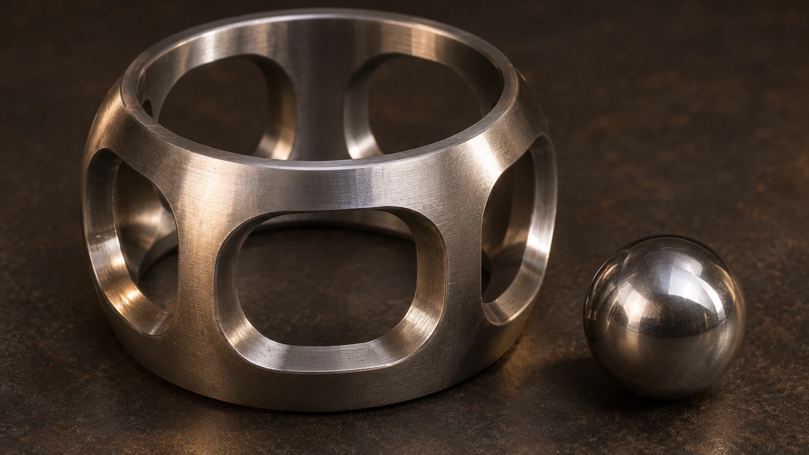
Discuss how the finishing method reaches the internal and external boundaries of each window. A method that improves the outside appearance may leave an inaccessible burr at an intersection. Inspection needs to reach that region too. If direct observation is difficult, agree an appropriate method before machining rather than discovering the access problem during final acceptance.
Surface condition also needs a location. Specify the relevant requirement on the surfaces where it matters, together with the delivered material state. A single finish symbol applied indiscriminately can add unnecessary effort on clearance areas while failing to communicate the intended contact condition. Avoid promising reduced wear from appearance alone; operating behavior requires its own evidence.
An assembly that binds needs a structured comparison
Consider an illustrative prototype that assembles freely at neutral but becomes tight during articulation. Begin by confirming the mating components, orientation, lubrication condition if specified for the check, and test fixture. Then compare the sphere relationship and window pattern with the drawing. Determine whether the observed contact belongs to the intended interface or an unintended edge.
Do not immediately enlarge every window. That could remove material from the wrong boundary or change a required contact relationship. Identify the location and direction of interference first. Compare the sample’s free-state geometry with its supported inspection state, and check whether finishing or material processing changed the shape. The corrective action should address the identified cause.
This is a hypothetical engineering scenario, not an account of a Jucheng project. It demonstrates why records should connect a symptom to measured geometry. A report saying only that the assembly was tight gives the next process engineer little basis for deciding whether to change a fixture, an allowance, a finishing operation, or the design itself.
Define the evidence that accompanies the sample
For a CV joint cage prototype review, provide the controlled model, drawing sections, mating ball and joint references, material specification, intended sample use, and required inspection records. Jucheng’s manufacturing review can address the proposed machined geometry and route against those inputs. Any specialized finishing or validation remains a project-specific agreement.
The inspection plan should separate individual dimensions, profile relationships, edge condition, and assembly checks. Record the drawing revision and the condition in which measurements were taken. An approved mating assembly can complement dimensional evidence, but a successful hand assembly does not demonstrate service life, high-load behavior, or conformity to an unspecified automotive standard.
Frequently asked questions
Can a CV joint cage be prototyped by CNC machining?
It may be a suitable route for a defined geometry or assembly study, depending on material, access, and required condition. Confirm the actual files and purpose. A machined development sample does not automatically reproduce the material history of a production part.
Are larger windows a reliable cure for binding?
No. Binding can involve the spherical relationship, window position, burrs, mating parts, or the test setup. Locate the interference and compare it with the drawing before changing the design.
Should final inspection happen before heat treatment?
Intermediate inspection can be useful, but final acceptance must represent the specified delivered condition. If processing can change geometry, the plan needs appropriate checks afterward as well.
Design reference
El published cage-forming patent ES2062950A2 describes one route involving guiding and window surfaces. It illustrates process alternatives, not a general production instruction or proof that any particular material or route meets a new joint’s requirements.

