


An orthopedic depth gauge can contain accurately machined parts and still show an inconsistent reading if its probe, sleeve, stop, and scale do not share the intended reference. The useful manufacturing question is how a physical contact at the working end becomes a readable displacement at the handle. That chain needs to remain defined through machining, marking, assembly, and inspection.
This guide is for instrument development and component procurement. It covers geometry, sliding behavior, scale placement, and prototype verification. It does not explain how to measure a patient’s anatomy or select a surgical screw. Clinical use, validated cleaning, biocompatibility, and device release require the responsible manufacturer’s approved processes and evidence.
Follow the measurement chain from the working end
Start with a sectioned assembly showing the probe or hook, the sleeve contact end, and the feature that moves relative to the scale. Identify the two physical references whose separation the instrument is intended to indicate. A drawing of the handle alone cannot establish that relationship. The contact convention belongs in the assembly definition.
The geometry may use a hooked tip or another design-specific contact. Describe the relevant shape, its orientation, and its connection to the sliding member. Do not assume every depth gauge has the same construction. Define what counts as the contact point or contact region in the design’s inspection method; a curved end can produce different readings under different presentation conditions.
Next trace the axial distances to the indicator and scale. Identify shoulders, seats, stops, threaded joints, or caps that contribute to the stack. State which features establish zero and which only retain the assembly. If a cap is replaceable, decide how its dimensional variation is controlled and whether replacement requires a verification step.
Sliding fit is a functional requirement with a defined state
The probe needs to move through its intended travel without a burr or local interference changing the response. That does not mean specifying the smallest possible clearance. The sleeve bore, probe straightness, surface condition, alignment, and assembly loading must be considered together. A loose fit and a sticky fit can both interfere with a useful indication, for different reasons.
Describe the condition used to assess motion. A dry prototype, an assembled instrument after an approved cleaning cycle, and a partially built component do not necessarily behave identically. The manufacturer should define the relevant state and acceptance method. Do not invent a universal sliding force or substitute a subjective statement such as “feels smooth” for a required test.
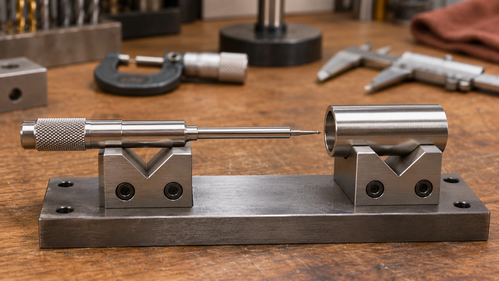
For slender components, handling can change the apparent result. Support the part appropriately during measurement and identify whether a straightness check applies before or after assembly. Clamping a flexible probe to force alignment can hide the condition being evaluated. Plan the support around the drawing’s intent rather than the convenience of a particular measuring machine.
Stainless steel selection includes processing and finishing
Specify the approved grade, incoming condition, and required final state. “Surgical stainless steel” is not a complete machining specification. Different grades can have different machining behavior and processing requirements. The component’s role, corrosion requirements, strength needs, and device-level evidence should guide the selection rather than an assumption that one alloy fits every instrument.
For manufacturing discussions, the stainless steel machining page provides the relevant material-service context. Confirm the exact grade and processing scope for the project. Do not infer medical-device approval, a validated reprocessing claim, or a particular hardness from that material category.
Finishing needs to preserve the measurement references and sliding interface. Deburring can alter a small tip; polishing can change an edge used to locate a scale or a contact surface. If a surface treatment is required, state whether acceptance dimensions apply afterward. Keep any dimensional allowance connected to an approved process rather than adding an arbitrary margin to the model.
Place the scale after defining zero
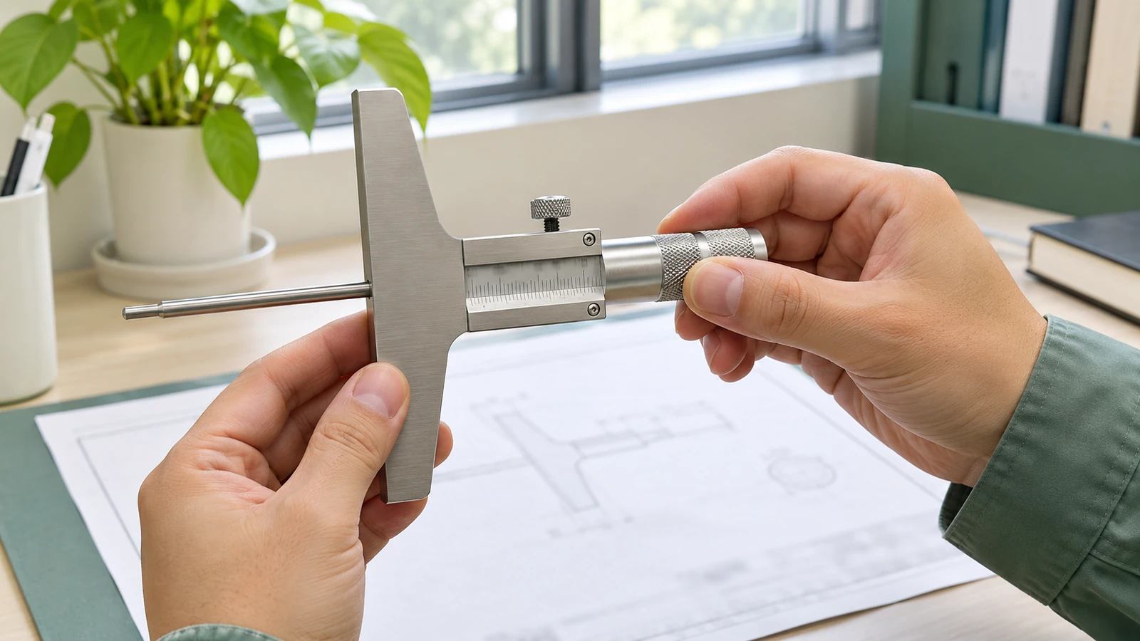
On an orthopedic depth gauge, a clear scale is useful only when its location corresponds to the actual measurement chain. Define the origin, increment, reading convention, and the surface or pointer used for reading. Include units and orientation in the controlled artwork. A supplier should not infer the zero point from the end of a convenient cylindrical feature.
Discuss whether marking is performed before or after final assembly and finishing. The answer depends on the construction and process. If marking before assembly, the stack must reliably place the scale relative to the working references. If marking after assembly, the locating method must still be controlled and repeatable. Neither sequence removes the need for verification.
Marking quality and dimensional accuracy are separate checks. Contrast, legibility, and durability may be required, but a high-contrast scale can still be shifted. Likewise, a correctly located mark may be hard to read. Define the inspection evidence for each requirement and avoid treating an attractive photograph of the scale as a calibration record.
Diagnose a changing reading with reference artifacts
Imagine a hypothetical development sample that reads consistently at one displacement but differs at another. Begin by checking the reference artifact and the presentation method. Confirm which surfaces are in contact and whether the probe follows the intended line. Then compare the zero relationship and the spacing of the relevant scale marks with the drawing.
A constant offset suggests a different investigation from an error that changes with travel. The first may involve the axial stack or scale origin; the second can involve spacing, alignment, play, or another mechanical effect. These are diagnostic possibilities, not proof of a cause. Preserve measurements across the required range and evaluate them against the approved acceptance method.
If readings change when the instrument is rotated or lightly handled, examine lateral play, contact geometry, and support. Do not correct the artwork before establishing whether the problem is mechanical. This example is illustrative, not a Jucheng case study. Its value is the separation of reference error, assembly behavior, and scale location before a component is remade.
Prepare an instrument-specific prototype order
For an orthopedic depth gauge development review, send the assembly model, component drawings, scale artwork, material and finishing specifications, reference convention, and intended sample purpose. Jucheng can review the machined component scope and manufacturing questions against those files. Calibration and device-validation responsibilities should be agreed separately.
The sample acceptance package should identify travel limits, inspection points, reference artifacts, assembled condition, and required records. If disassembly is part of the design, consider whether reassembly can change zero or motion and include a suitable check where required. A verified component dimension and a verified instrument reading are complementary results; neither should silently stand in for the other.
Frequently asked questions
What controls zero on an orthopedic depth gauge?
The specified working contacts and the mechanical stack connecting them to the reading feature. The exact construction determines the references. Zero should come from the controlled assembly definition and verification method.
Can scale marking compensate for a sticky probe?
No. Marking cannot repair inconsistent mechanical movement. Investigate the sliding surfaces, burrs, alignment, support, and assembly condition before changing the scale.
Does a material certificate prove instrument accuracy?
No. It provides material information. Accuracy needs evidence from the defined assembled measurement chain and acceptance method, using suitable references and conditions.
Should a probe and sleeve be inspected separately?
Component inspection is useful for understanding dimensions and causes of variation. Assembly verification is also needed when the required result depends on their interaction. The drawing and quality plan should specify both scopes.
Product context
gSource’s depth-gauge catalog shows designs with different ranges and removable components. It supports the need to define a particular construction; its product claims do not establish Jucheng certification or validation.

