


El mecanizado de bloques de metal y plástico en bruto para convertirlos en componentes funcionales de alta precisión requiere un profundo conocimiento de la cinemática de las herramientas de corte sustractivas y los requisitos de configuración. La implementación de pautas críticas para el diseño para la creación rápida de prototipos CNC garantiza que los presupuestos de desarrollo estén protegidos de horas de mecanizado innecesarias y de altos riesgos de rotura de herramientas. Muchos equipos de ingeniería diseñan carcasas electrónicas intrincadas o soportes estructurales que se ven perfectos en CAD 3D pero que son físicamente imposibles de tallar con cortadores redondos giratorios. Resolver estos límites geométricos temprano garantiza que los prototipos físicos puedan fresarse de manera rápida y económica en mesas de máquina estándar.
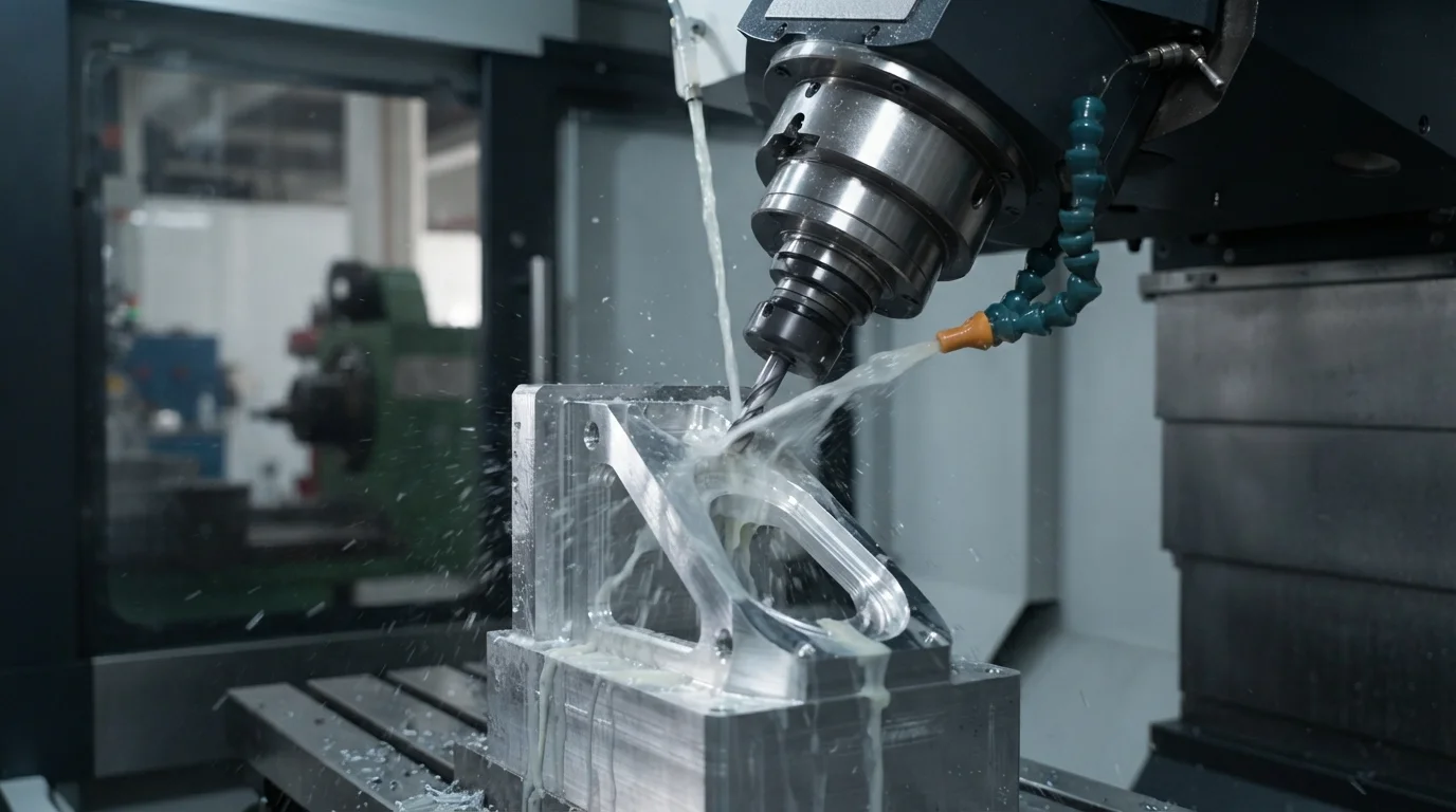
La obtención de piezas de validación física con características de fresado optimizadas ayuda a los grupos de ingeniería a confirmar los requisitos de holgura de ensamblaje de manera realista. Los especialistas en mecanizado CNC evalúan las direcciones de acceso de las herramientas, los métodos de sujeción del material en bruto y las relaciones profundidad-diámetro de las cavidades utilizando simuladores digitales avanzados. Eliminar las características de diseño que requieren fresas de micro-mecanizado especializadas o complejos dispositivos de sujeción personalizados reduce drásticamente los plazos de desarrollo generales. Los grupos de diseño técnico aseguran acabados superficiales impecables y una resistencia mecánica robusta al abordar los límites del proceso de manera sistemática.
Tabla de Contenidos
1. Física de la herramienta rotativa y radios de esquina internos
2. Limitación de cavidades profundas y relaciones profundidad-diámetro
3. Reducción de configuraciones de sujeción y fresado CNC multieje
Física de la herramienta rotativa y radios de esquina internos
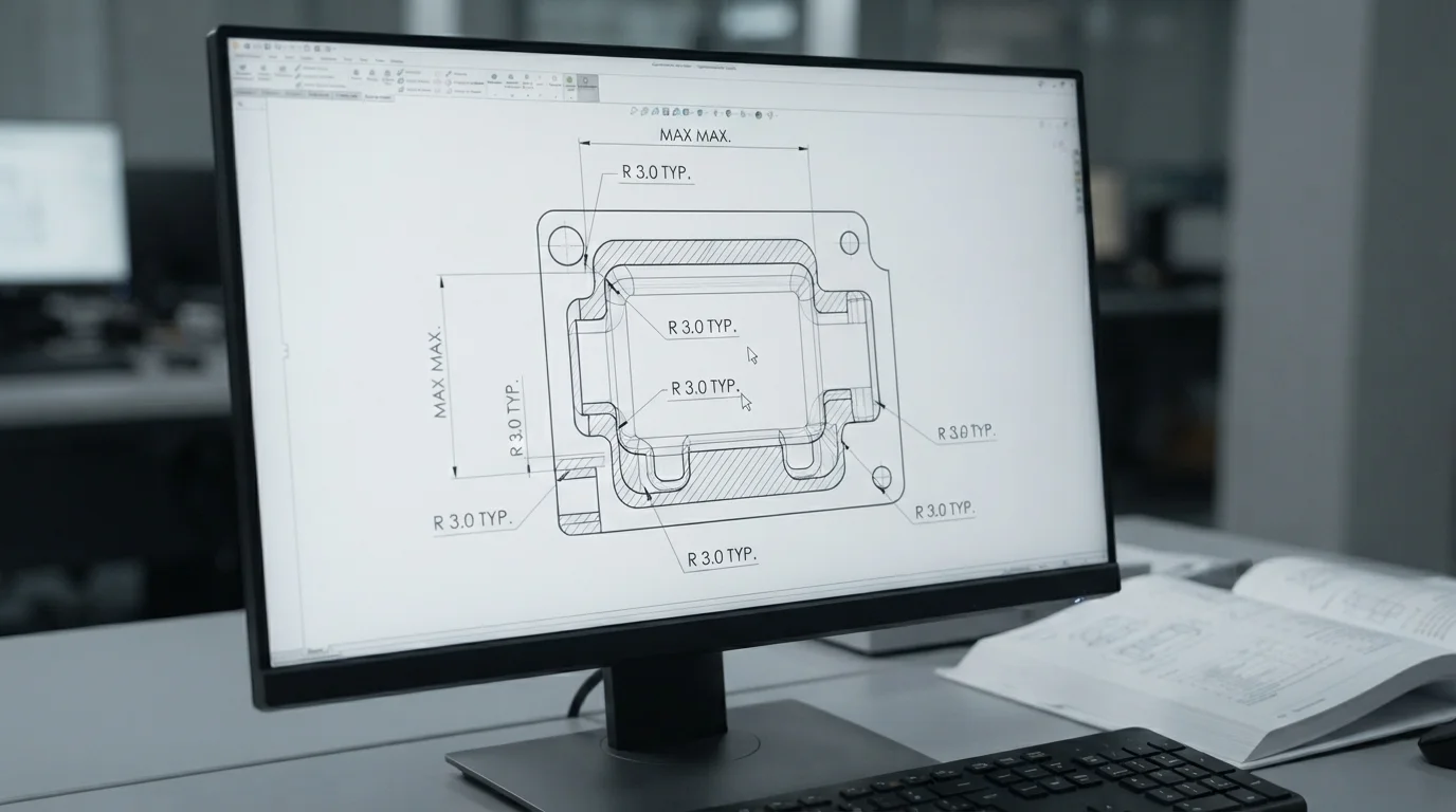
Pregunta: ¿Por qué las máquinas CNC no pueden fabricar esquinas internas absolutamente afiladas de 90 grados? Los cortadores rotativos son redondos, lo que significa que deben dejar un radio de empalme que coincida con el radio de la herramienta de corte en cada esquina interna.
Las fresas son cilindros rotativos que se desplazan a lo largo de trayectorias de herramienta coordinadas, lo que hace físicamente imposible cortar esquinas internas verticales afiladas de 90 grados. Intentar forzar una esquina interna vertical afilada requiere procesos secundarios costosos como electroerosión por hilo (EDM) o cincelado manual, lo que aumenta el costo y los plazos de entrega. Los diseñadores deben especificar radios de empalme generosos en todas las paredes verticales para permitir que los cortadores rotativos eliminen material suavemente. Dimensionar las esquinas internas ligeramente más grandes que el radio de la fresa evita el atasco y la vibración de la herramienta durante transiciones rápidas en las esquinas.
Especificar un radio interno mínimo de 1,5 mm permite que fresas estándar de 3,0 mm realicen cortes profundos rápidamente sin rotura de la herramienta. Adaptar las características geométricas a las dimensiones estándar de las herramientas es una regla fundamental al el diseño para la creación rápida de prototipos CNC. Los grupos de diseño mecánico reducen los gastos de ingeniería ajustando las esquinas de los componentes de acoplamiento para despejar perfiles de ranura redondeados.
Limitación de cavidades profundas y relaciones profundidad-diámetro

Pregunta: ¿Cuál es la profundidad máxima recomendada de una cavidad para componentes fresados por CNC? La profundidad de la cavidad generalmente debe limitarse a cuatro veces el diámetro de la fresa para evitar la desviación de la herramienta, vibraciones severas y acabados superficiales rugosos.
Los bolsillos internos profundos requieren herramientas de corte largas y delgadas que son altamente susceptibles a la deflexión física y la vibración rotacional bajo presión de corte. La deflexión de la herramienta degrada las precisiones dimensionales, causa marcas de roce dimensionales y aumenta los valores de rugosidad de la microsuperficie. La implementación de principios de diseño de prototipado rápido principios asegura que las cavidades profundas tengan una relación profundidad-ancho inferior a cuatro para proteger la estabilidad estructural. El diseño de bolsillos poco profundos con transiciones inclinadas de piso a pared permite que las fresas estándar corten a altas velocidades de manera segura.
Seleccionar la geometría estructural correcta implica equilibrar las profundidades de los bolsillos con las velocidades de corte generales y las selecciones de herramientas. Los prototipos de alta precisión médicos, automotrices y aeroespaciales se fresan a partir de bloques sólidos de metal utilizando longitudes de herramienta estándar para mantener bajos gastos. Esta tabla de comparación técnica destaca los parámetros de mecanizado base críticos para el éxito de la creación de prototipos sustractivos:
| Característica de Mecanizado | Estándar de Diseño Recomendado | Límite de Prototipado | Riesgo de Ingeniería Principal |
|---|---|---|---|
| Radios de Esquina Internos | ≥ Radio de herramienta + 0.5 mm | 0.5 mm mínimo | Alto desgaste de herramienta, vibración de cortador, marcas en esquinas |
| Profundidad a Ancho de Bolsillo | Relación 4:1 máxima | Relación 8:1 extrema | Deflexión severa de herramienta, rotura de cortador |
| Threaded Hole Depth | 1.5 to 2.0 times hole diameter | 3.0 times hole diameter | High tap tool breakage, excessive tapping hours |
Threaded features also demand conservative depth limits, as standard taps can easily break when cutting deep holes in tough metals like titanium or stainless steel. Tapping threads beyond twice the nominal hole diameter provides no additional holding strength while increasing tool extraction risks. Mechanical designers lower manufacturing expenses by designing shallow, standard-threaded bores across all internal structural mount sites.
Reducing Clamping Setups and Multi Axis CNC Milling
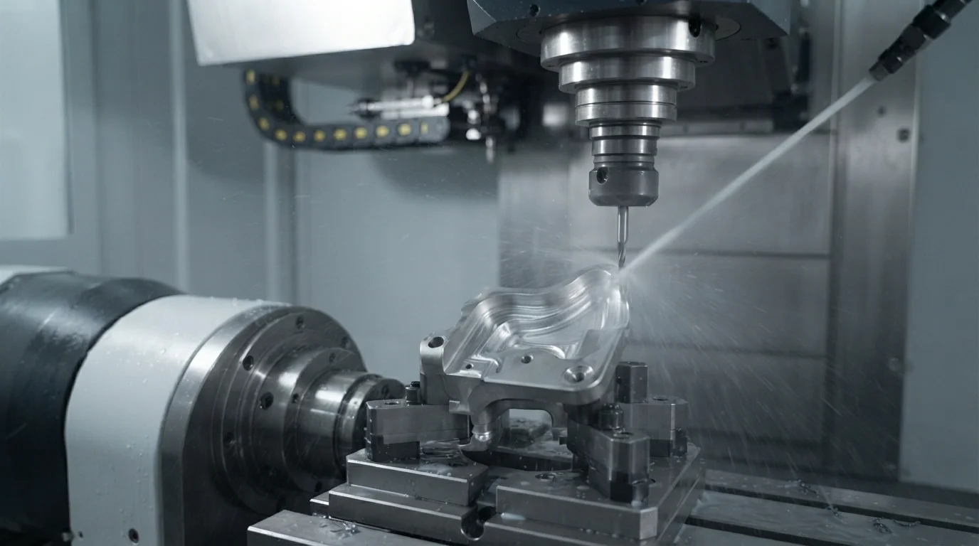
Question: How does reducing clamping setups lower machining costs? Fewer part rotations minimize human setup errors, preserve geometric coordinate alignments, and accelerate turnaround times.
Clamping setups directly influence overall subtractive manufacturing expenses, as each physical rotation of the raw billet blocks requires manual labor. Part designs that require machining from six different directions demand six separate setups, which increases costs and setup time. Designers must attempt to align as many machined features as possible along a single coordinate axis to maximize cutting efficiency. Minimizing setups ensures part tolerances remain highly repeatable across complex mating features.
Sourcing professional manufacturing partners helps streamline complex component geometries by utilizing simultaneous multi-axis milling setups. Jucheng Precision operates a fully equipped manufacturing facility containing 150+ CNC machines, including 25 high-precision Haas/Mazak de 5 ejes systems to mill complex linkages. Factory expertise in el diseño para la creación rápida de prototipos CNC ensures structural assemblies undergo meticulous 24-hour free DFM reviews to optimize tool paths. Cutting complex geometries in a single setup preserves sub-micron coordinate repeatabilities across intricate medical, automotive, and consumer electronics programs.
Preguntas Frecuentes (FAQ)
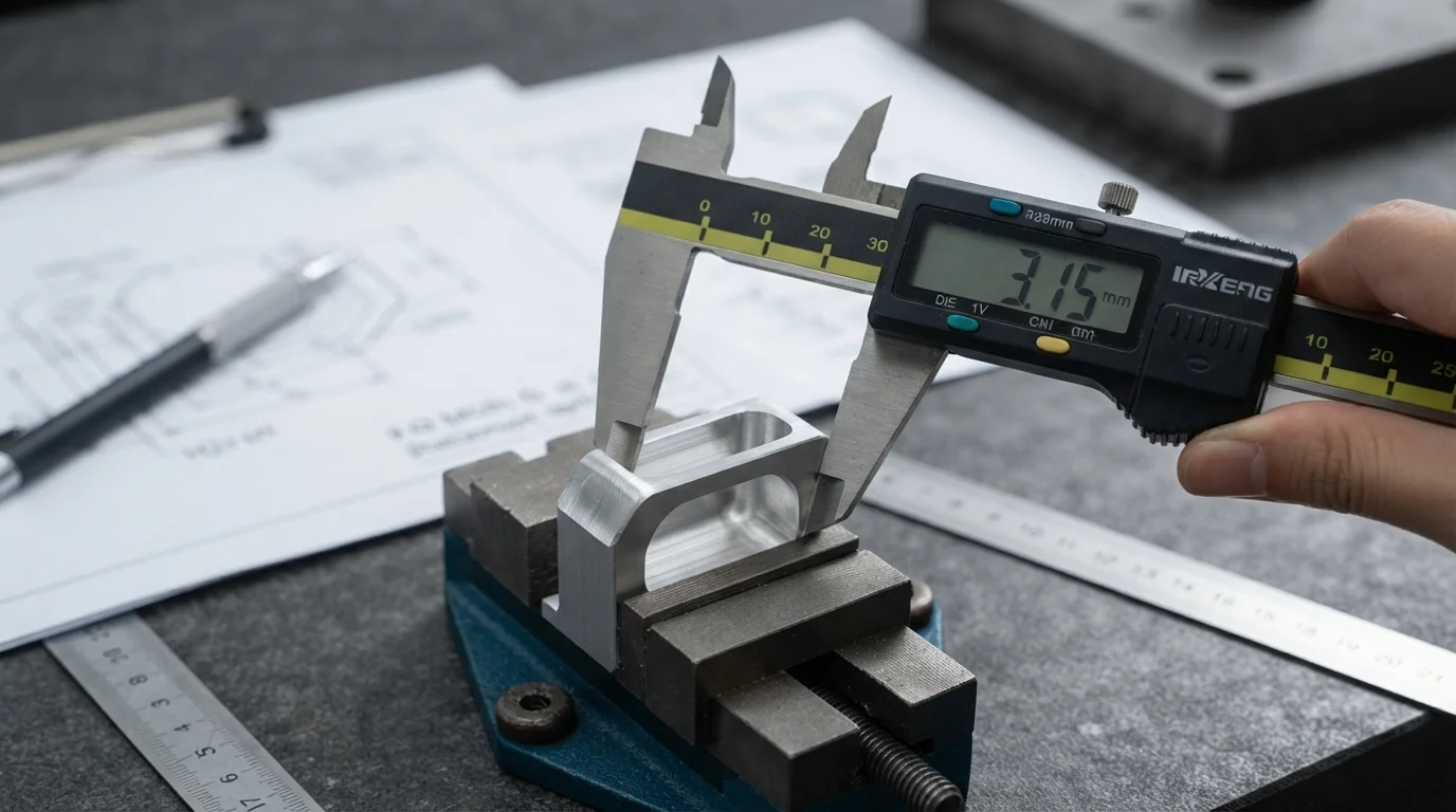
Why are standard cutting tool diameters preferred over custom sizes?
Standard cutter sizes are always stocked in CNC facilities, eliminating specialized sourcing delays and custom tool expenses. Designing internal radii to match standard metric and imperial endmills ensures rapid turnarounds and lower overall manufacturing costs.
How can sharp internal 90-degree corners be avoided in mating slots?
Incorporar cortes de alivio en forma de hueso de perro o T en las esquinas de las ranuras permite que los componentes de acoplamiento cuadrados se deslicen completamente. Los cortes de alivio permiten que la fresa rotativa limpie los límites de las esquinas de manera limpia, evitando la necesidad de operaciones secundarias de electroerosión.
¿Cuál es el ángulo de desmoldeo óptimo para cavidades mecanizadas por CNC?
El fresado CNC sustractivo no requiere ángulos de desmoldeo porque la herramienta de corte no arrastra contra las paredes de la cavidad como en el moldeo. Las paredes de la cavidad se pueden mecanizar en ángulos verticales perfectos de 90 grados sin rayones ni problemas de liberación de la pieza.

