


Establecer geometrías estructurales correctas representa un hito crítico para prevenir fallas mecánicas físicas durante la evaluación temprana del hardware. Elegir un grosor de pared adecuado para prototipado rápido protege los presupuestos de desarrollo al evitar deflexión de piezas estructurales, curvatura del material o marcas de hundimiento cosméticas. Muchos grupos de productos enfrentan retrasos severos en el desarrollo porque especifican paredes ultrafinas que se imprimen con agujeros o vibran violentamente bajo la presión de la fresa CNC. Resolver las limitaciones de grosor bruto temprano asegura que los modelos a escala física transiten suavemente hacia herramientas de producción en masa.
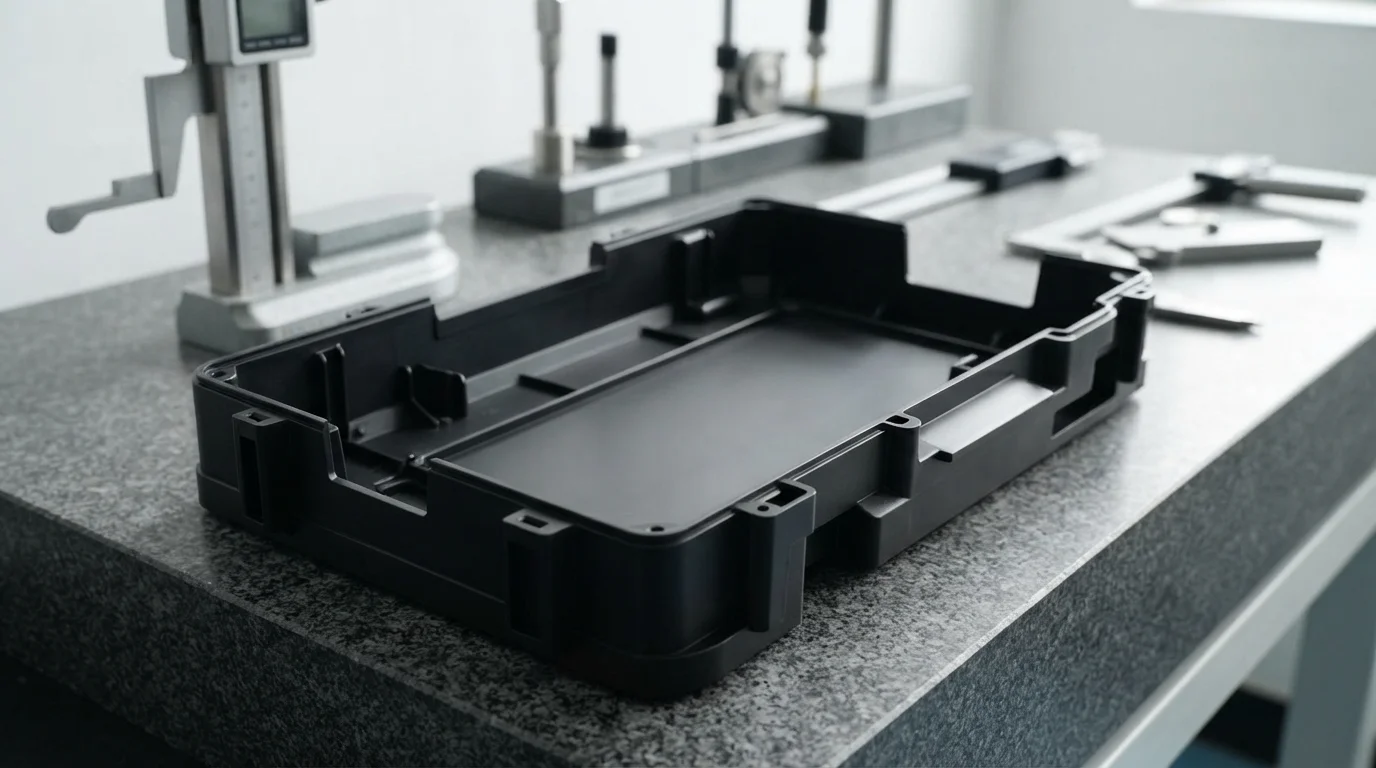
Obtener piezas de validación física con secciones transversales optimizadas ayuda a los departamentos de ingeniería a confirmar los cálculos de tensión mecánica de manera realista. Los especialistas en fabricación evalúan la contracción potencial de la resina, las rutas de disipación de calor y las ubicaciones de las líneas de partición utilizando barridos avanzados de simulación CAD. Resolver las discrepancias de grosor de pared durante los ciclos de validación funcional garantiza que el componente físico funcione exactamente como el hardware moldeado por inyección producido en masa. Los grupos técnicos de ingeniería aseguran rutas de fabricación estables y rentables al abordar los límites geométricos de manera sistemática.
Tabla de Contenidos
1. Deflexión de Micro Piezas y Limitaciones de Impresión Aditiva
2. Mínimos de Fresado CNC Sustractivo y Vibración de Herramienta
3. Reglas de Oro de Uniformidad para Producción de Moldeo Puente
Deflexión de Micro Piezas y Limitaciones de Impresión Aditiva
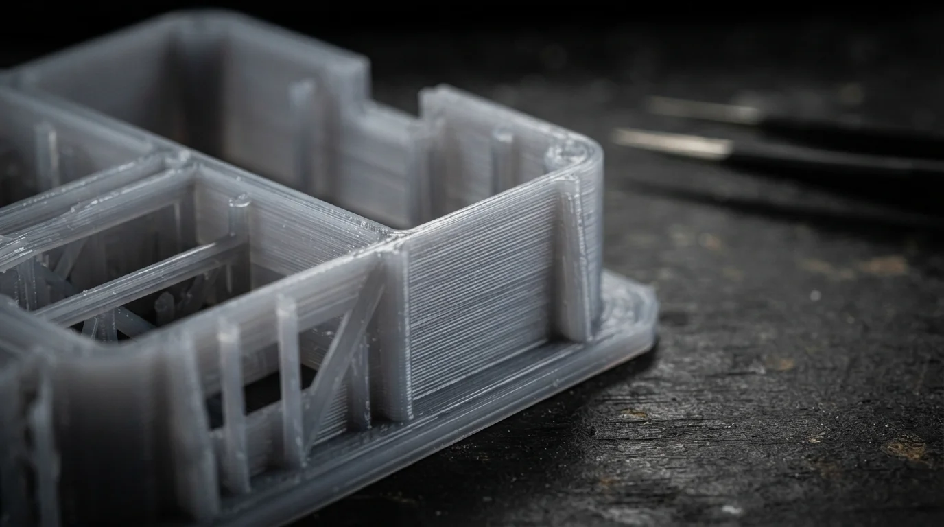
Pregunta: ¿Cuál es el grosor de pared mínimo posible para la impresión 3D de fotopolímero? La tecnología SLA de estereolitografía puede lograr grosores de pared mínimos de 0.8 mm para paredes soportadas, pero las características no soportadas requieren al menos 1.5 mm para evitar el curvado.
Las tecnologías de fabricación aditiva ofrecen una libertad geométrica notable, sin embargo, las contracciones térmicas y la física de apilamiento de capas imponen límites dimensionales claros. Las resinas de fotopolímero utilizadas en estereolitografía se contraen a medida que curan bajo barridos de láser UV, causando que las paredes delgadas y no soportadas se curven o deformen. Los métodos de fusión en lecho de polvo como la sinterización selectiva por láser sufren distorsión localizada inducida por calor si las paredes son demasiado delgadas para soportar el material bruto circundante. Los diseñadores estructurales deben tener en cuenta estas limitaciones básicas del polímero para evitar problemas de acoplamiento en el ensamblaje.
Obtener maquetas tempranas requiere que los diseñadores de productos asignen espacios generosos alrededor de los ajustes a presión entrelazados y los botones con núcleo hueco. Adherirse a límites básicos generosos asegura que las carcasas impresas en 3D se ensamblen limpiamente sin necesidad de limado o lijado manual. Gestionando grosor de pared adecuado para prototipado rápido projects systematically prevents engineering teams from specifying impossible micro-clearances on additive parts. Early dimensional allowances ensure different plastic parts mate together seamlessly during form and fit validation.
Subtractive CNC Milling Minimums and Tool Vibration
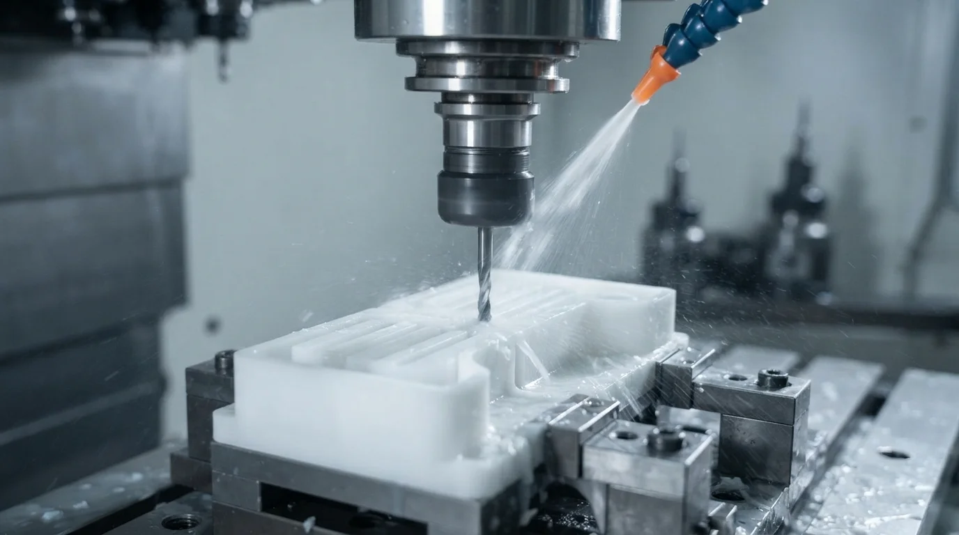
Question: Why do thin walls vibrate during CNC machining? Rotational cutter forces induce severe physical vibrations in thin metal or plastic features, resulting in scuff marks and dimensional inaccuracies.
Precision mechanical assemblies requiring high specific strength, airtight seals, or sliding linkages demand dimensional repeatabilities that additive methods cannot deliver. Implementing thorough principios de diseño de prototipado rápido principles ensures critical structural mounting plates are routed on multi-axis CNC milling centers. Subtractive machining avoids the thermal distortion issues of 3D printing, enabling operators to hold micro-tolerances with extreme repeatability. Standard machined clearances prevent internal components from buckling under dynamic load configurations.
Selecting the correct manufacturing process involves balancing wall tightness with overall tooling expenditures. High-precision medical, automotive, and aerospace prototypes are milled from solid billet blocks to preserve isotropic material properties. This technical comparison table outlines minimum wall thickness standards across key rapid fabrication methods:
| Método de fabricación | Minimum Wall (Supported) | Minimum Wall (Unsupported) | Riesgo de Ingeniería Principal |
|---|---|---|---|
| Impresión 3D SLA | 0.8 mm | 1.5 mm | Material curling, thermal warping, structural breakage |
| Impresión 3D SLS | 1.0 mm | 1.5 mm | Unmelted powder entrapment, localized distortion |
| Moldeo al vacío | 1.5 mm | 2.0 mm | Air bubble trapping, incomplete mold cavity filling |
| CNC Machining (Plastics) | 1.5 mm | 2.5 mm | Heavy cutter chatter, friction-induced melting |
| CNC Machining (Metals) | 0.5 mm | 1.0 mm | Severe tool vibration, dimensional scuff marks |
Cutting deep, thin pockets in plastic or aluminum components requires slow feed rates and small cutter diameters to avoid tool breakage. Mechanical designers lower manufacturing expenses by maintaining robust wall dimensions that resist rotational cutting pressure easily. Generous radius values allow standard endmills to cut profiles quickly without inducing tool vibration or deflection.
Uniformity Golden Rules for Bridge Molding Production
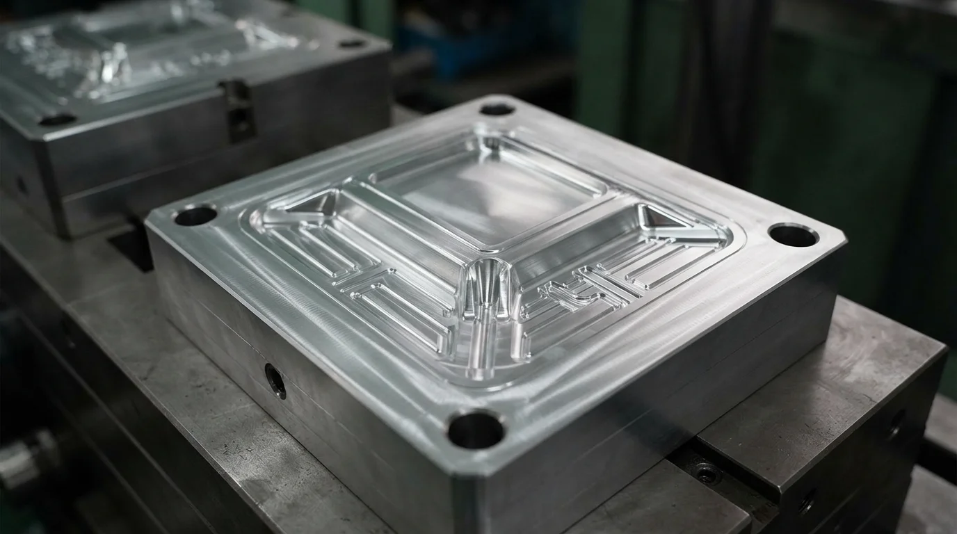
Pregunta: ¿Cuál es la causa principal de las marcas de hundimiento cosméticas en componentes moldeados por inyección? Las secciones gruesas localizadas se enfrían más lentamente que las paredes delgadas circundantes, creando vacíos internos que tiran de la superficie del polímero hacia adentro.
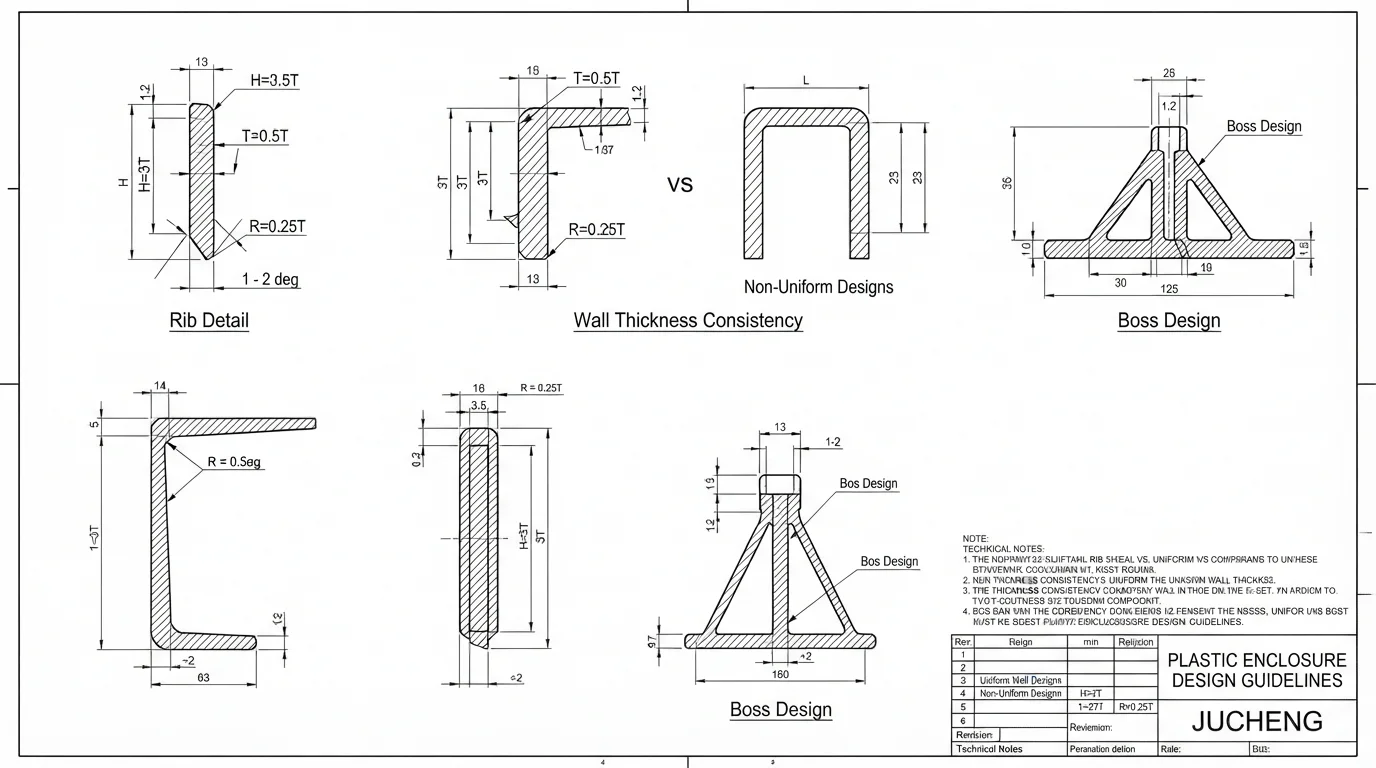
Maintaining uniform cross-sections represents the golden rule of plastic injection molding, preventing uneven volumetric shrinkage and post-mold warpage. Thick plastic hubs or solid bosses must be cored out and supported by thin reinforcing ribs to ensure consistent polymer solidification. Rib thicknesses are generally restricted to 60 percent of the nominal wall to avoid visible sink marks on the opposite show face. Sourcing early dimensional validation ensures interlocking features align perfectly under physical dynamic loads.
Cumplir con estrictas grosor de pared adecuado para prototipado rápido guidelines ensures that target dimensional tolerances remain realistic across different manufacturing processes. Jucheng Precision operates a fully equipped manufacturing facility containing 150+ CNC machines, including 25 high-precision Haas/Mazak de 5 ejes systems to mill complex linkages. Factory teams deliver comprehensive DFM gratuito las 24 horas analyses to resolve draft angles, wall margins, and gating marks before mold core cutting begins. Specialized utillaje rápido molds deliver high-quality injection-molded components within 4 to 15 days, helping design groups hit aggressive launch schedules.
Preguntas Frecuentes (FAQ)
¿Cuál es el espesor de pared óptimo para carcasas de plástico estructural?
Las carcasas de plástico moldeadas o fresadas generalmente funcionan mejor con un espesor de pared de 1.5 mm a 3.0 mm. Dimensionar las paredes dentro de este rango equilibra la resistencia al impacto mecánico con las características generales de flujo de polímero y las velocidades de enfriamiento.
¿Cómo se mecanizan piezas de metal CNC de pared delgada sin deformarse?
Machining operators run high-speed spindles with continuous synthetic coolant spray to eliminate friction-induced heat. Rigid work-holding fixtures support thin-walled features completely, preventing tool-induced vibration during milling passes.
¿Por qué las paredes desiguales causan que los prototipos de plástico se deformen?
Thick plastic sections cool much slower than adjacent thin walls, creating localized internal vacuum stresses during polymer solidification. Uneven cooling pulling forces twist the molded component, leading to post-mold dimensional warping.

