


Reforzar carcasas de plástico con nervaduras estructurales y cubos de montaje roscados representa una técnica de ingeniería obligatoria para agregar rigidez estructural sin aumentar el espesor de pared nominal. Sin embargo, las características internas mal diseñadas tiran del polímero superficial hacia adentro a medida que el plástico se solidifica, creando marcas de hundimiento cosméticas antiestéticas o vacíos internos. Obtener comentarios técnicos tempranos de DFM asegura que los fabricantes de moldes evalúen los diámetros del núcleo del cubo y las relaciones de pared de las nervaduras antes de cortar el metal del núcleo. La ejecución meticulosa de las prácticas de diseño de nervaduras y cubos en el moldeo rápido garantiza que sus piezas de plástico salgan de las cavidades blandas planas, resistentes y completamente sin imperfecciones.
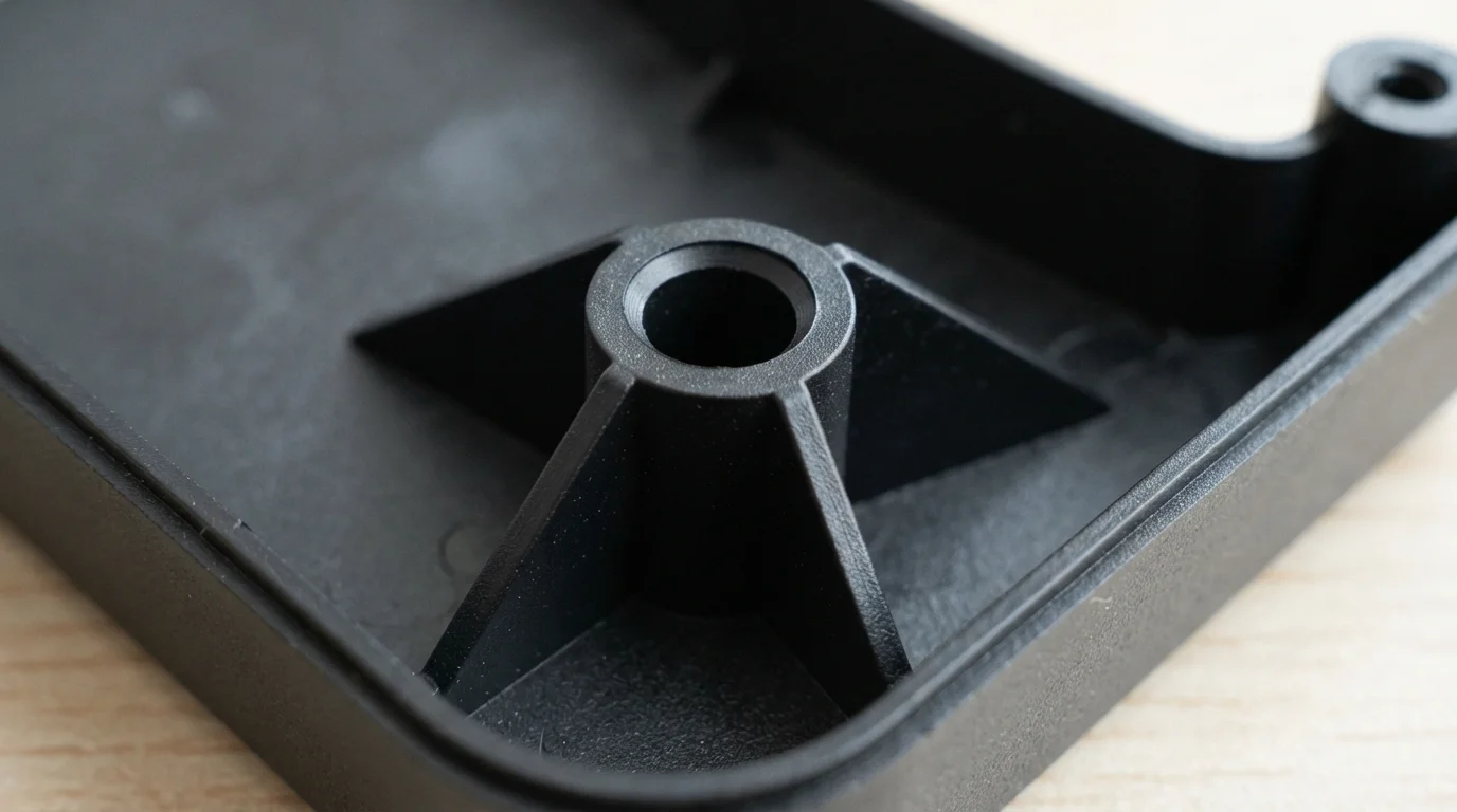
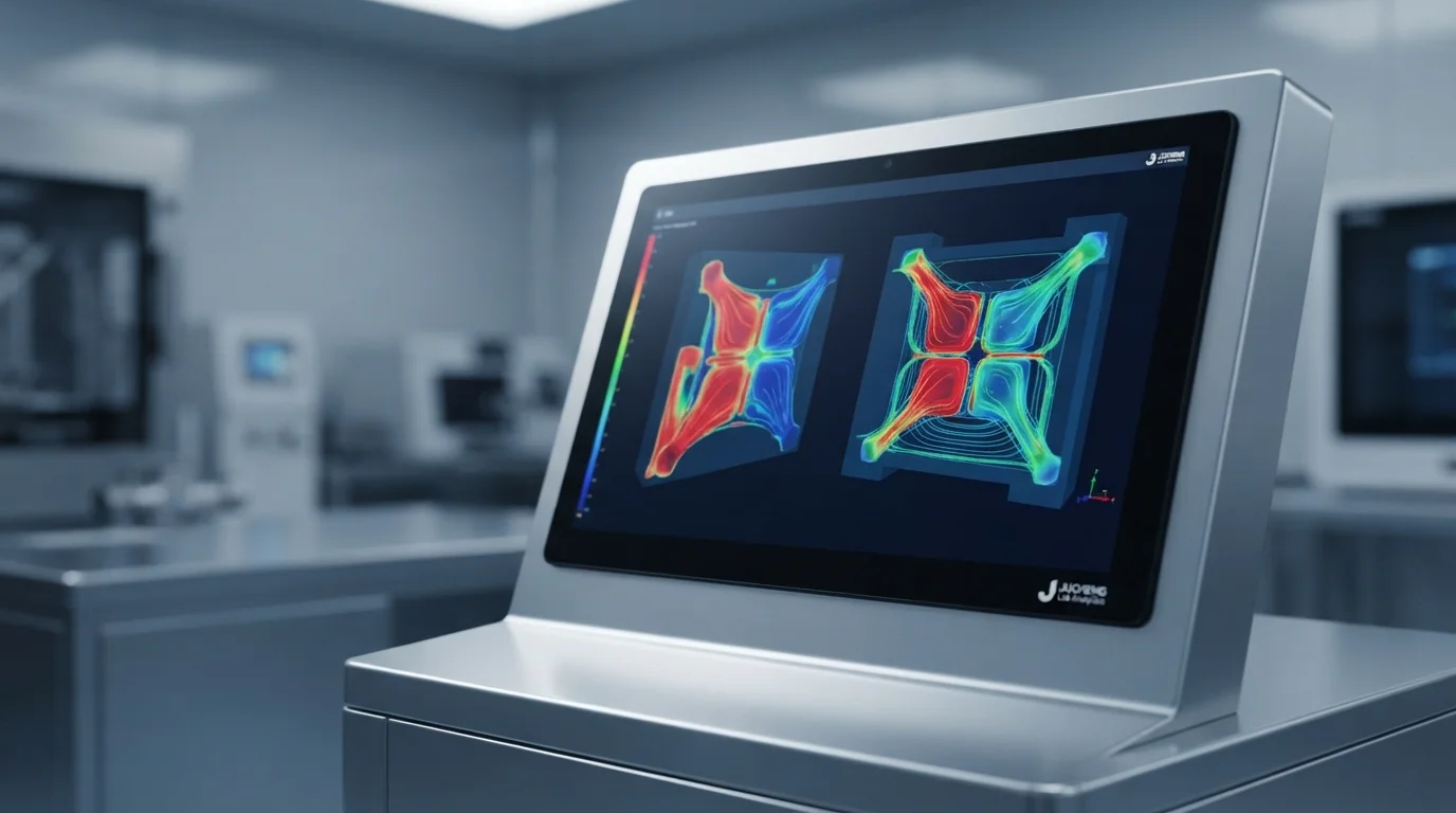
Cortar geometrías CAD tridimensionales complejas con precisión permite a los fabricantes de moldes experimentados analizar líneas de separación, ángulos de desmoldeo y espesores de pared utilizando software avanzado de simulación de flujo de molde. Seleccionar métodos de fabricación temporal apropiados equilibra las propiedades de la materia prima con tiempos de entrega rápidos durante las pruebas en etapas tempranas. Obtener sus componentes de un socio experimentado asegura que los cambios de diseño se propaguen de manera segura en todas las etapas. Exploremos la regla de espesor del 60%, las reglas de refuerzos para cubos y los ajustes de geometría que previenen la formación de vacíos.
Tabla de Contenidos
1. La regla del 60 por ciento de espesor y la física de las marcas de hundimiento
2. Diseño de cubos de tornillo para fijación mecánica
3. Prevención de vacíos y marcas de hundimiento con geometría adecuada
La regla del 60 por ciento de espesor y la física de las marcas de hundimiento
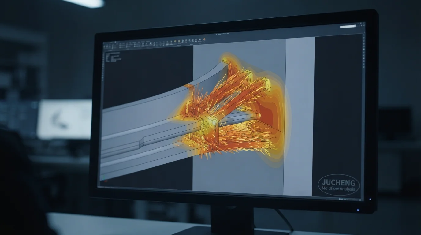
Pregunta: ¿Por qué el espesor de la base de la nervadura no debe exceder el 60% de la pared adyacente? Las raíces de nervaduras gruesas se enfrían más lentamente que las paredes nominales, creando fuerzas de contracción térmica internas que tiran de las superficies visibles hacia adentro.
Agregar nervaduras estructurales proporciona una rigidez de carga excepcional mientras mantiene paredes exteriores delgadas y uniformes que se enfrían rápidamente dentro de las cavidades del molde. Obtener revisiones tempranas de DFM permite a los fabricantes de moldes verificar que los espesores de la base de las nervaduras permanezcan restringidos al 50 o 60 por ciento de las paredes nominales adyacentes. Las raíces de nervaduras gruesas crean concentraciones de masa plástica localizadas que tardan más en enfriarse, resultando en marcas de depresión superficial severas en las caras visibles opuestas. Adherirse a las diseño de pautas para herramientas rápidas asegura que sus modelos CAD equilibren la resistencia mecánica con una estética superficial impecable.
Ejecutar los parámetros de diseño de nervaduras y cubos en el moldeo rápido con precisión requiere integrar relaciones geométricas específicas directamente en el modelo CAD. Los parámetros estructurales clave para el diseño de nervaduras incluyen:
- Relación de base nominal—El espesor de la base de la nervadura debe permanecer entre el 50% y el 60% del espesor de pared nominal para evitar hundimientos cosméticos
- Altura máxima de la nervadura—La altura de la nervadura no debe exceder 3 veces el espesor nominal de la pared para evitar problemas de mecanizado en ranuras profundas
- Radios de filete en la base—Los radios de filete en las uniones de las nervaduras deben medir de 25% a 40% del espesor nominal de la pared para prevenir grietas por tensión
Diseño de cubos para tornillos para fijación mecánica
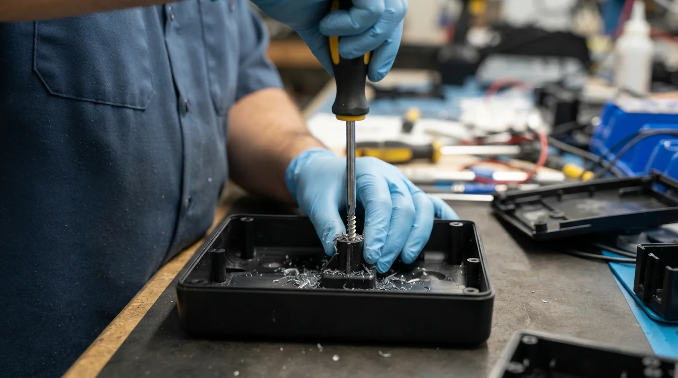
Pregunta: ¿Cómo se diseñan los cubos de plástico para tornillos para evitar el agrietamiento durante la inserción de la rosca? Los cubos deben estar ahuecados hasta la pared base, con espesores de pared exterior mantenidos al 60% del espesor nominal y diámetros internos ajustados a las especificaciones de la rosca del tornillo.
Los cubos cilíndricos sirven como puntos de montaje principales para tornillos de acero autorroscantes, placas de circuito impreso y subconjuntos internos. La obtención de piezas funcionales moldeadas de plásticos de ingeniería sólidos como ABS, Nailon (PA), o Policarbonato (PC) proporciona un comportamiento auténtico del material bajo tensión circunferencial de formación de rosca. Los cubos sólidos, sin ahuecar, crean concentraciones masivas de plástico que inducen marcas de hundimiento severas y vacíos internos. Ahuecar los cubos completamente hasta la pared base mantiene un enfriamiento uniforme del polímero y previene fracturas por tensión circunferencial.
El soporte de cubos altos independientes con refuerzos triangulares evita la flexión de la característica durante el atornillado o la expulsión de la pieza. Esta tabla de comparación técnica describe los parámetros de diseño de cubos recomendados según el tipo de material:
| Tipo de Resina | Relación de pared exterior del cubo | Relación de diámetro del agujero interior | Requisito de soporte con refuerzos |
|---|---|---|---|
| ABS (Impacto Medio) | 60% del espesor nominal de la pared | 80% del diámetro mayor de la rosca | Recomendado para cubos más altos que 2.5 veces el diámetro |
| Nailon 6 (PA6-GF30) | 50% of nominal wall | 85% of thread major diameter | Mandatory due to high fiber stiffness |
| Policarbonato (PC) | 60% del espesor nominal de la pared | 82% of thread major diameter | Mandatory to prevent hoop stress cracking |
Preventing Voids and Sink Marks with Proper Geometry
Question: What is the primary difference between a sink mark and a vacuum void? Sink marks pull external show-face surfaces inward, whereas vacuum voids form sealed air bubbles inside thick plastic sections.
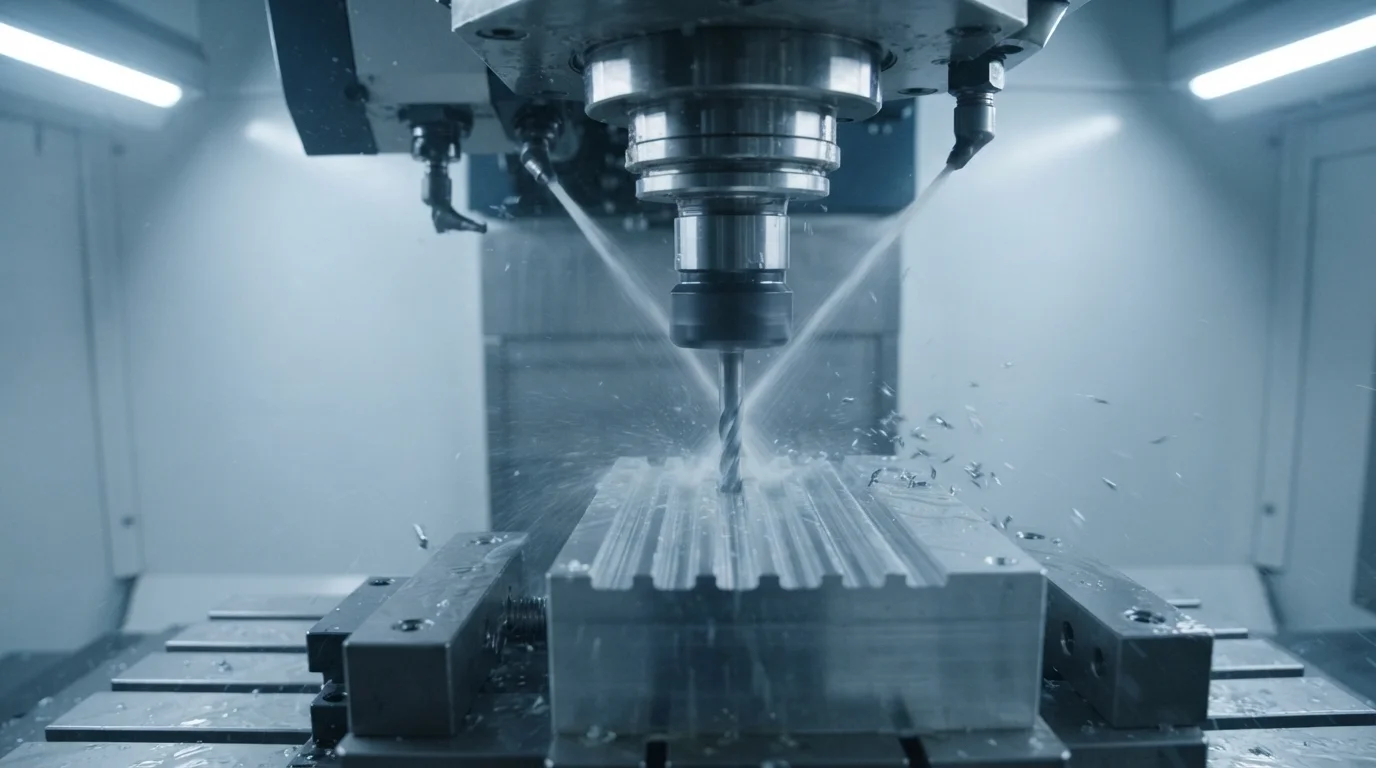
Applying proper ribs and bosses design rapid molding guidelines protects your plastic enclosures from internal air bubbles and surface sink marks. Sourcing a dedicated Servicio de utillaje rápido using aluminum AL7075 or soft P20 Acero para Herramientas cores delivers genuine injection-molded components from production-grade resins within weeks. Machining narrow, deep rib slots into soft Aluminio mold plates requires high-speed Servicio de mecanizado CNC spindles to clear metal chips without cutter deflection. Sourcing rapid tooling allows product developers to validate gating, parting lines, and draft angles under real machine pressures.
Jucheng Precision apoya a las startups de mecatrónica proporcionando revisiones DFM gratuito las 24 horas integrales que analizan ángulos de desmoldeo, uniformidad de paredes, ubicaciones de compuertas y factores de contracción. Obtener piezas Servicio de prototipos parts or soft-alloy molds allows engineering groups to validate designs before committing to high-volume production. Best practice CAD guidelines for preventing voids and sink marks include:
- Coring thick bosses completely—Eliminating solid plastic hubs prevents internal vacuum voids during thermal cooling
- Connecting bosses to side walls—Linking standalone bosses with thin connecting ribs increases structural load distribution
- Incorporating 1.5-degree rib drafts—Tapering rib side walls ensures clean release from aluminum cavities without scuffing
Asociarse con un especialista certificado Servicio de moldeo por inyección specialist ensures your finished hardware matches the premium software experience. Sourcing your quotes manually ensures experienced engineers analyze your 3D STEP files to find additional ways of eliminating sink marks and lowering tooling costs. Custom components undergo rigorous coordinate metrology checks to confirm exact dimensional compliance. Sourcing high-quality prototypes ensures your designs are built to withstand severe dynamic forces safely.
Preguntas Frecuentes (FAQ)
Why should rib base thickness not exceed 60% of the adjacent wall?
Designing ribs with a base thickness of 50% to 60% of the main wall represents the most effective way to eliminate sink marks on show faces. Sizing ribs thinner than 50% may impede polymer flow, causing short shots during fast injection cycles.
How do gusset ribs support tall standalone bosses?
Tall standalone bosses require support from two or four triangular gusset ribs to prevent bending during thread-forming screw installation. Gussets distribute driving torque forces across adjacent walls, preventing stress whitening or boss snapping.
Why are deep rib slots difficult to CNC mill in mold core steel?
Deep rib channels require high-speed CNC milling spindles running with continuous coolant mist to flush metal chips out of deep slots. Sourcing early DFM reviews ensures rib draft angles are sufficient to prevent tool binding during aluminum mold machining.

