


A water pump impeller is not automatically a machining job just because it has vanes. The right route depends on what the prototype must prove, how the hub and blade geometry are defined, what material is specified, and how the part will be inspected. Machining can be useful when the design needs controlled interface features or a short iteration path, while other processes may suit different geometries or quantities.
This guide is for engineers comparing prototype routes and preparing a review package. It does not calculate pump performance or prescribe a blade design. Hydraulic targets, material limits, balance requirements, and validation criteria must come from the responsible product team.
Decide what question the prototype must answer
Start with the intended use of the sample. Is it meant to verify the shaft or hub interface, check clearance inside a housing, inspect blade geometry, assemble with a seal, or support a planned performance test? Each objective requires different evidence. A part that proves envelope fit may not be suitable for a flow test or durability evaluation.
For a water pump impeller, define the features tied to that objective before choosing how to make the part. The central bore, hub length, mounting or retention feature, blade envelope, and any balancing datum may matter in different ways. Do not treat every visible surface as equally critical or assume the production drawing already defines every prototype requirement.
If the design is changing, record the revision and identify which characteristics must remain comparable between iterations. Changing stock, process, or finishing can alter the measured part, so comparisons are meaningful only when the inspection setup and acceptance criteria are consistent.
When machining is a practical prototype route
Machining is worth considering when the specified material is available as stock, the geometry is accessible to cutters, and the design needs accurately formed interfaces for a fit or assembly check. It can support rapid changes to a hub, bore, face, or blade envelope without committing to dedicated production tooling. Whether it is practical for a particular impeller depends on blade depth, curvature, wall thickness, tool reach, setup access, and the required surface condition.
For a water pump impeller with open, accessible geometry, CNC milling may be considered to create the hub and blade surfaces from a controlled blank. A more complex shape may need multiple orientations or a different process plan. The phrase “five-axis” should not be treated as a solution by itself: the model, cutter access, fixturing, and inspection method still determine whether the design is manufacturable and what tradeoffs remain.
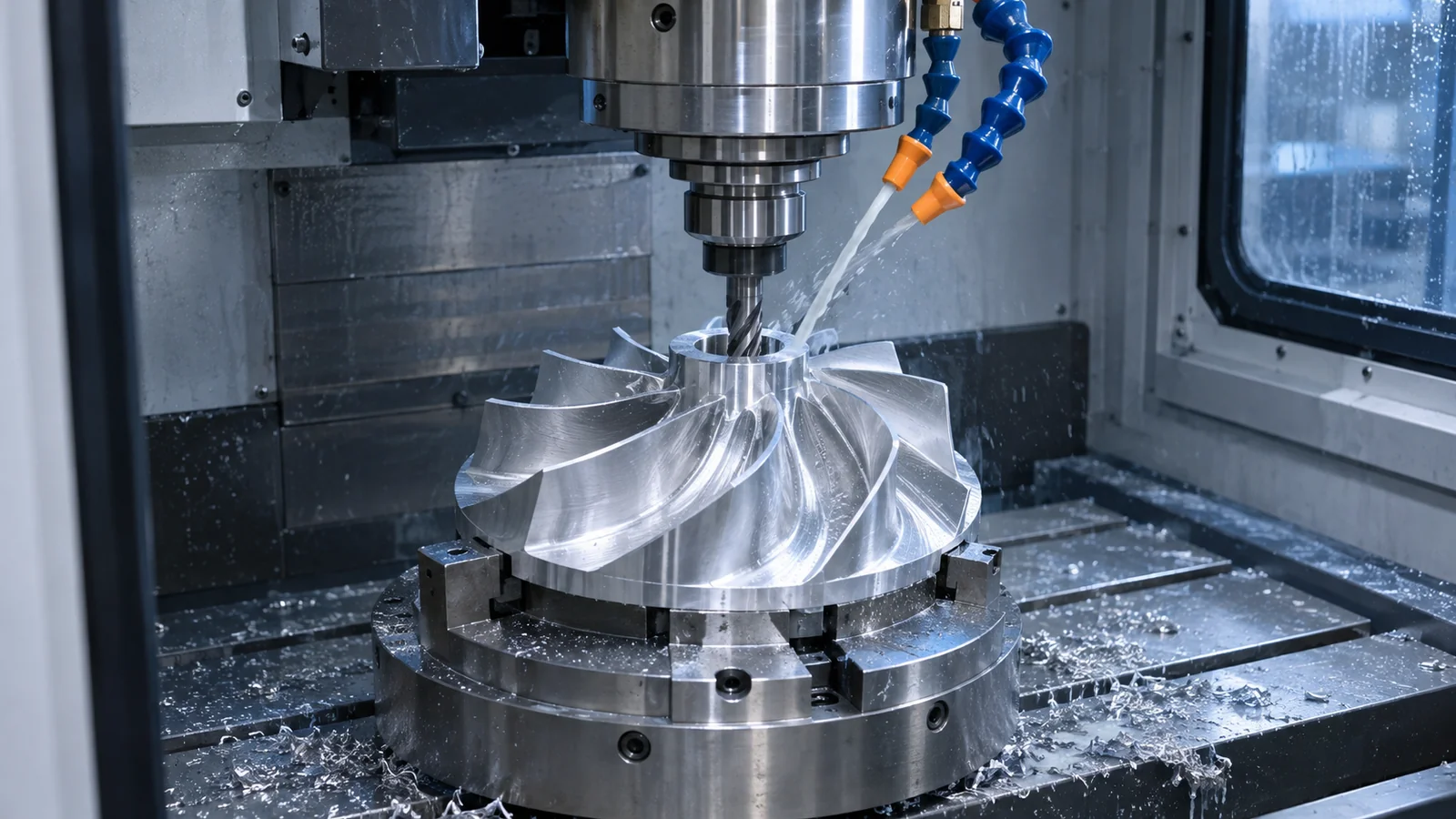
Machining may be less attractive when the part contains very thin blades, deep enclosed passages, or a geometry that removes a large amount of material from expensive stock. In those cases, compare a suitable additive, molding, casting, or formed route if it is within the design and project scope. The goal is not to force a preferred process but to choose one that answers the prototype question with acceptable risk and cost.
The site’s CNC milling service information describes a relevant process category. It is general service context, not a promise that any blade form, alloy, surface finish, or hydraulic result can be achieved without design review.
Separate the hub interface from the blade form
The hub often provides the clearest functional reference. Identify the axis and end face that locate the impeller in the assembly, then relate the blade envelope and any retention feature to that frame. If a shaft, key, spline, threaded fastener, or other connection is used, the released drawing should identify the applicable interface rather than leaving the supplier to infer it from appearance.
For a water pump impeller, tolerance decisions should follow function. A bore fit or axial seat may control assembly, while a noncontact blade surface may be governed by profile or envelope requirements. A design may also need to control runout, concentricity, or balance, but those terms should appear only when the responsible engineering team defines the measurement method and acceptance limit.
Blade geometry can be difficult to inspect using simple contact measurements. If the design requires a surface profile, define the datum alignment and data comparison method. If only a clearance envelope is needed, a simpler inspection approach may be enough. Clear requirements prevent a supplier from reporting a dense point cloud that does not answer the actual engineering question.
Material and finishing decisions must stay tied to the drawing
Do not choose a material from the word “water pump.” The product specification may call for a specific aluminum alloy, stainless steel, polymer, or another material based on temperature, fluid compatibility, strength, corrosion, and cost requirements. A prototype made from a different grade can demonstrate geometry while failing to represent service behavior.
If the drawing specifies aluminum, identify the exact alloy and temper. If it specifies stainless steel, identify the grade and condition. The site’s stainless steel machining information can provide general machining context, but it does not replace the pump’s material specification. Material substitutions, heat treatment, coatings, or balancing changes need approval from the design owner.
Finishing can change critical dimensions or edge conditions. State whether the final bore and seating face are measured before or after treatment, identify masked surfaces if applicable, and define edge requirements near blades and hubs. If balancing is part of the project, specify the assembly condition, reference, and acceptance criteria instead of assuming a machined impeller is balanced merely because its geometry is symmetric.
Build an inspection plan around the test objective
Inspection should first confirm the datum features, hub interface, overall envelope, and other dimensions listed as critical. A coordinate measuring machine or optical method may suit some blade profiles; a bore gauge, fixture, or other instrument may suit the hub. Selection depends on access, tolerance, material, and the required evidence.
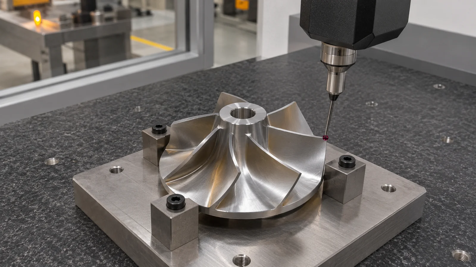
For a water pump impeller, the inspection report should say how the part was aligned to the CAD model or drawing, which surfaces were measured, and which areas were not accessible. A functional fit check can supplement dimensional results, but it should not be reported as a flow or endurance test. If a performance test is planned, define the rig, fluid, operating condition, and acceptance criteria separately through the responsible test organization.
Preserve drawing revision, material traceability requested for the project, inspection setup, and any approved deviations. When a blade or hub feature changes, keep the old and new measurement definitions clear so the engineering team can tell whether the observed difference came from the design or the measurement process.
Questions to resolve before ordering
Before requesting a prototype, provide the controlled model and drawing, material and condition, quantity, test objective, critical interfaces, finish requirements, balancing expectations if any, and inspection deliverables. Identify whether the part is for packaging, fit, visual review, or a defined test. State which features may be adjusted during iteration and which must remain fixed.
A useful manufacturing review should flag thin walls, inaccessible blade surfaces, setup changes, stock limitations, and measurement gaps. It should also distinguish a geometric prototype from a production-intent component. No single machining route automatically proves hydraulic performance, fatigue life, corrosion behavior, or regulatory suitability.
Machining is most valuable when it delivers the evidence the team actually needs: a controlled hub interface, a revised blade envelope, or a repeatable fit check. A water pump impeller should be routed based on that engineering purpose, the specified material, and the geometry’s inspectability—not on the part name alone.
Worked route comparison: a fit prototype and a performance prototype are different jobs
Hypothetical engineering scenario, not a Jucheng customer case: a team has a revised impeller model and wants a sample quickly. One group needs to confirm that the hub seats on the shaft and clears the housing; another expects the same sample to support a pump performance comparison. Those objectives should not be bundled into one vague purchase description.
For the fit question, define the hub bore or connection, axial seating face, outside envelope, and clearance surfaces. A machined prototype may be practical if the specified stock and blade geometry can be reached and inspected. The inspection report can then answer whether the interface and envelope match the controlled model. It cannot say whether the pump moves a required flow or meets an efficiency target.
For a performance comparison, the team must also define the test setup, operating conditions, fluid, assembly, and acceptance method. Material and surface condition should represent the intended comparison. If those elements are not controlled, two test results may reflect different rigs or assemblies rather than the design revision. The engineering team should decide whether a machined shape is sufficiently representative or whether another route is needed.
Compare routes using the evidence required, not only lead time. Machining can support accessible features and design iteration; a different route may be more suitable for a production-like blade form, volume, or material. A geometry that requires extensive stock removal, thin unsupported vanes, or inaccessible surfaces can change both cost and inspection risk. Ask the supplier to identify these constraints before selecting the process.
FAQ: water pump impeller prototype machining
When is machining preferable to a cast or molded route?
It may suit a short prototype run when the specified material is available as stock, the geometry is accessible, and the objective is to evaluate interfaces or a defined design change. Production volume, blade form, material, surface condition, and validation goals can point to another process.
Can CNC machining make any curved impeller blade?
No universal answer applies. Tool reach, curvature, wall thickness, setup access, material, and inspection method determine feasibility. A controlled model and drawing are needed for a supplier to assess the actual geometry.
Does a machined impeller come balanced by default?
No. Balance requirements depend on the design and assembly condition. If balance is required, specify the reference, configuration, method, and acceptance criteria; do not infer balance from a visually symmetric part or a dimensional report.
What should be measured on an early fit prototype?
Measure the interfaces tied to the test objective: typically the hub connection, seating face, envelope, and specified clearances. For a blade-profile study, define the alignment and comparison method. Keep those dimensional checks separate from hydraulic performance testing.

