


Una aircraft engine oil pump moves lubricant through a system that may include pressure and scavenge functions, filters, relief valves, bearings, and return passages. In a gear-type design, a pair of meshing gears rotates inside a housing, and the small clearances around the gears influence leakage and flow behavior. For a component drawing, the key manufacturing question is how gear bores, cover faces, ports, drive features, and the mounting datum remain aligned through the specified process sequence.
This article is a component-engineering guide, not maintenance or airworthiness advice. The engine designer and approval holder define the design requirements, qualification, and acceptance criteria. A machined prototype or inspection report cannot establish aircraft certification, flight suitability, or pump performance without the corresponding approved test program.
Understand the pump architecture before reading the drawing
Aircraft lubrication systems vary. Some use engine-driven gear pumps; dry-sump systems may use separate pressure and scavenge elements, and other architectures may use different pump types. The number of stages, drive arrangement, relief function, and housing layout depend on the engine. The drawing package should identify which pump element is represented and how it interfaces with the engine accessory case and oil circuit.
The FAA powerplant handbook describes a gear-type oil pump as two meshing gears rotating within a housing, with one gear connected to a drive shaft and the housing clearances kept small. Newer handbook material also notes that pressure and scavenge elements may be combined and that gear-to-wall and side clearances are important to output. These are architectural principles, not numerical tolerances for a specific aircraft engine. The controlled design data remains authoritative.
Before quoting a prototype, request the current drawing revision, material and heat-treatment requirements, port definitions, drive-interface details, and specified inspection or test evidence. If the drawing refers to an assembly datum or a mating accessory case that is not supplied, identify how the datum is to be simulated. An assumed bolt pattern or port location can produce a part that appears complete but does not represent the intended interface.
Relate the gear bores, cover face, and ports
The gear axes are established by the pump’s bearing bores or bushings. Their parallelism and position, along with the end faces and side plates, determine the geometric space around the gears. The cover face and mounting plane locate the pump against the accessory case or housing. Inlet and outlet ports connect the internal flow path to the larger system. The drawing should express these relationships using datums that match the assembly, rather than dimensioning each feature from unrelated edges.
Port location often has both geometric and functional consequences. A port may need to align with an external passage, gasket, or seal; its center location alone may not capture sealing-land width or fastener clearance. Likewise, an internal cross-drilled passage may intersect a gear cavity or relief channel. The drawing and model should clearly identify through-holes, blind holes, plugs, chamfers, and any required edge condition so manufacturing and inspection can distinguish intentional geometry from breakout.
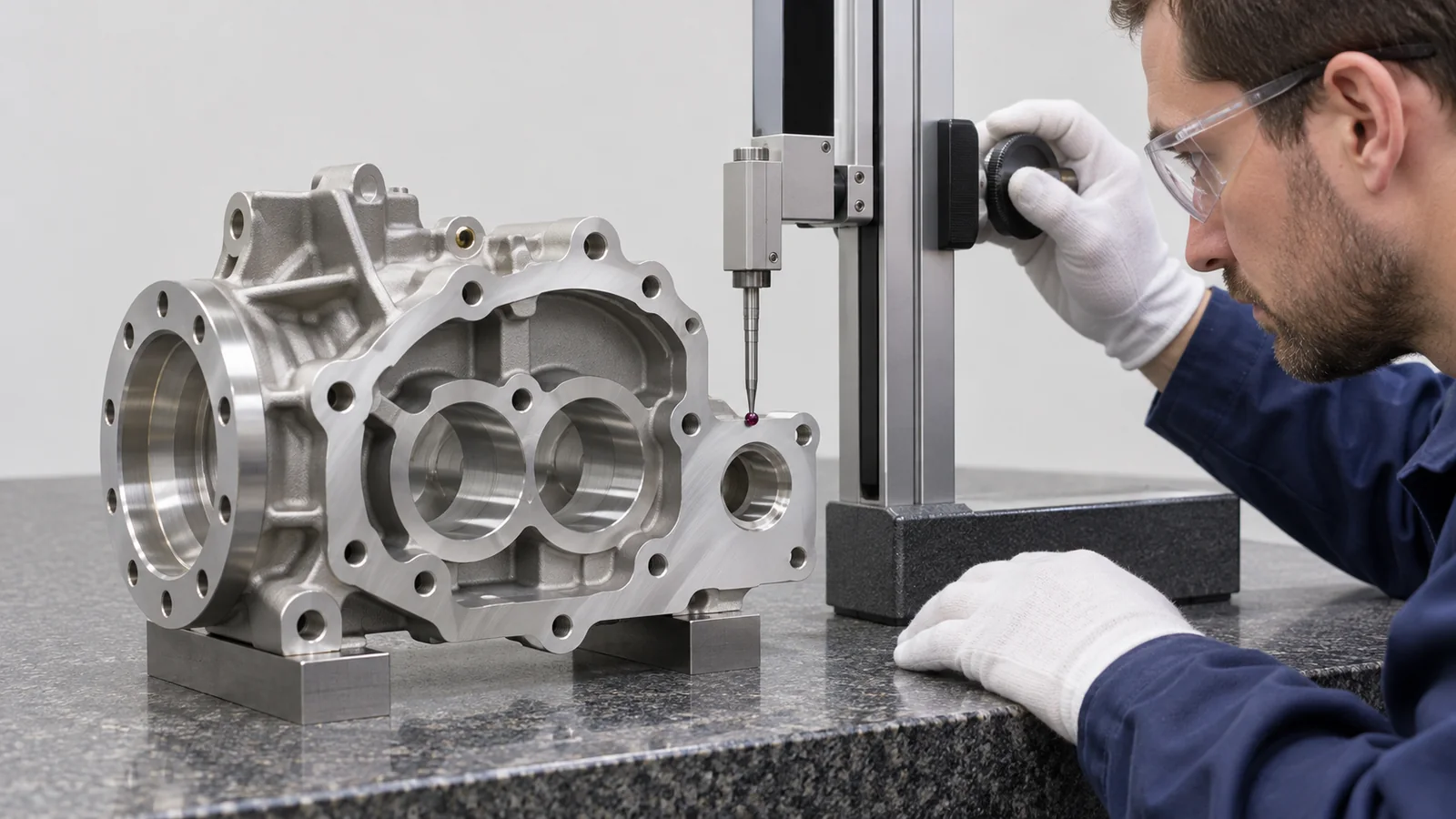
Aerospace fluid components on the site, such as the guide to aerospace hydraulic manifold ports and passages, illustrate why passage layout, datum selection, and inspection access should be discussed together. A manifold is not an oil pump, but the interface-planning questions overlap where a component combines precision bores and fluid ports.
Clearance is a design input, not a shop-floor guess
Gear-to-housing, gear-to-side-plate, and shaft-support clearances affect leakage and mechanical interaction. Research on external gear pumps examines how lubricating gaps and operating conditions influence performance. The important manufacturing lesson is that clearance values belong to the pump design and its operating envelope; a supplier should not select them from a generic article or a visually similar housing.
Dimensional inspection should therefore report the features that define the clearance stack: bore size and location, gear cavity dimensions, cover or side-plate position, and relevant flatness or surface finish if specified. If the customer requires a performance test, the test fluid, temperature, speed, pressure, inlet condition, fixture, and acceptance criteria must be defined by the design authority. A dimensional report is not a flow test, and a generic leak check is not equivalent to a validated pump performance test.
Thermal effects can change operating clearances. Material expansion, oil temperature, pressure loading, and housing deformation may matter to design calculations, but a prototype machine shop should not invent thermal compensation values. If the drawing uses a reference temperature or requires a stabilized measurement condition, record it. Otherwise, ask the customer which measurement conditions control acceptance.
Choose the sequence to protect critical geometry
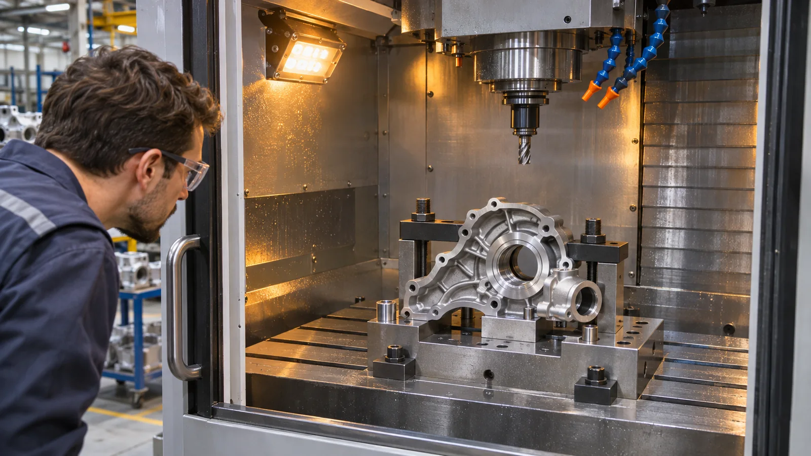
For a machined housing prototype, a typical planning discussion begins with the mounting datum and main gear cavity, then considers the bearing bores and ports. The exact order depends on stock form, wall thickness, access, and required tolerance. A casting or near-net blank may have a different route from a block-machined prototype. This sequence is an engineering planning option, not a claim that one method is universally correct.
Thin walls around the gear cavity can distort under clamping or after material removal. The workholding plan should distribute support, avoid loading seal faces, and establish datums that remain stable as the cavity opens. If the housing is removed and reoriented to machine ports or mounting faces, a repeatable datum-transfer method is needed. The inspection plan should identify whether the part is measured in a free state, on a fixture, or with a cover and fasteners installed.
If the pump uses inserts, bushings, dowels, or a separate cover, distinguish the component dimensions from the assembled dimensions. Pressing a bushing or installing a dowel can change a bore or position. State whether critical features are measured before installation, after installation, or after final assembly. Record the actual configuration associated with each report.
Plan inspection evidence around the intended use
- Mounting plane, register, bolt pattern, and port-to-mounting relationships.
- Gear bore diameters, axis spacing, parallelism, and cavity profile where specified.
- Cover or side-plate face position and any specified flatness or finish.
- Port size, location, sealing land, thread, and passage intersections.
- Material, heat-treatment, coating, and traceability records required by the drawing.
- Any flow, leakage, or pressure test with the complete controlled test conditions.
For an aircraft engine oil pump, choose a CMM, bore gauge, height measurement, profilometer, dedicated fixture, or other method according to the characteristic and tolerance. A CMM report may show bore position but does not automatically verify surface finish, internal passage cleanliness, or pump performance. If internal passages require inspection or cleaning evidence, specify the method and record separately.
For broader prototype route discussion, the main-site CNC machining overview is relevant to accessible machined features. Actual feasibility depends on the drawing, material, dimensions, and documented quality requirements; no aviation approval or certified-supplier status is implied here.
Questions to resolve with the design authority
Can a machine shop set the gear clearance from the handbook?
No. Handbooks explain typical architectures. The pump drawing and approved engineering data define the required clearance for a specific design.
Does a dimensional inspection prove oil flow or pressure?
No. Dimensional inspection verifies specified geometry. Flow or pressure performance requires a separate controlled test with defined fluid, temperature, speed, pressure, and acceptance limits.
What should a prototype request include?
Current drawings, material and condition, interface datums, port and passage details, required reports, prototype purpose, and any approved test procedure the supplier is expected to perform.
Conclusión
A clear aircraft engine oil pump plan links gear bores, cavity, cover, ports, and mounting interface to a datum scheme that represents assembly. It keeps design-controlled clearances separate from shop assumptions and distinguishes dimensional evidence from performance testing. Those boundaries make prototype results useful while leaving qualification and airworthiness decisions with the responsible engine program.

