


A propellant line clamp has to retain a tube without turning a support into a new source of stress, leakage risk, or thermal disturbance. It sits at the intersection of fluid-system safety and spacecraft structure: the line must stay within its route, the clamp must accommodate the defined movement, and the contact must not damage the tube or its insulation.
That is why spacecraft propellant line clamp design begins with the fluid-system owner’s controlled tube specification and operating envelope. A generic saddle shape cannot establish allowable contact pressure, thermal movement, cleanliness, or compatibility with propellant. Those inputs must come from the responsible engineering authority.
Contents
- Start with the tube and fluid-system data
- Decide what the support is meant to restrain
- Allow for movement without losing location
- Protect the tube at the clamp interface
- Preserve thermal and contamination controls
- Translate the support into controlled geometry
- Check the assembly under the right conditions
Start with the tube and fluid-system data
Collect the tube outside diameter, wall construction, material, surface condition, insulation, bend geometry, joining method, and allowable support conditions. Also identify operating and non-operating temperature ranges, pressure-system constraints, cleanliness requirements, and any approved contact materials. The line owner should provide these details along with the route and interface definition.
Clarify whether the clamp supports a bare tube, an insulated tube, or a line with a local protective sleeve. The contact geometry and retention method differ. A clamp designed for a nominal diameter may not retain a tube with coating or insulation installed, so acceptance should be based on the final configuration.
Keep fluid compatibility and structural design separate but coordinated. The clamp may never contact the propellant directly, yet its material, finish, debris generation, and installation process can still affect the surrounding system. Do not infer compatibility from a generic alloy or polymer name.
Decide what the support is meant to restrain
Some supports locate a line at a defined point; others allow controlled sliding while limiting transverse motion. A hard-fixed clamp can transfer thermal strain into a tube or fitting if the line is expected to expand. A sliding support can reduce axial restraint but must still prevent unwanted motion and maintain clearance.
Map each support along the route and identify its function. Mark fixed points, guided points, and areas where movement is permitted. The system analysis should establish how loads and movement are distributed. The drawing should not leave an assembler to decide whether a clamp is tightened firmly or left loose.
Check nearby fittings, valves, flexible sections, and instrument ports. A support located too close to a fitting may concentrate bending or limit access for joining and inspection. The support location should follow the defined load path and service strategy, not just a convenient panel location.
Allow for movement without losing location
Temperature change can alter tube length and position. Vibration and vehicle flex can add dynamic movement. The permitted motion depends on route geometry, tube material, wall, joints, temperature profile, and system requirements. A single universal gap or sliding allowance is not appropriate.
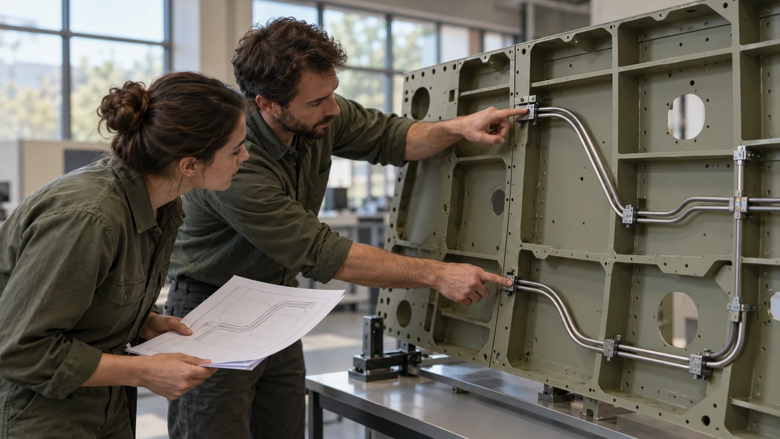
Use the line analysis to determine which direction of movement is expected at each support. If the design uses a slotted clamp or low-friction interface, define the travel, orientation, and retention method. Check that the line cannot migrate into a panel, neighboring equipment, or a sharp edge over the allowed movement range.
When the tube is fixed at one point and guided elsewhere, show that arrangement in the assembly model and note it on the drawing. A misplaced support can reverse the intended load path. If the line route changes in a later revision, revisit the restraint plan rather than copying support locations from the previous layout.
Protect the tube at the clamp interface
Contact pressure and edge condition deserve explicit attention. A narrow contact band can create local stress; a sharp split line or burr can damage a tube coating or insulation. Consider a broad saddle, a compliant liner, or another approved interface when needed. The fluid-system authority must approve any material that contacts or sits near the line.
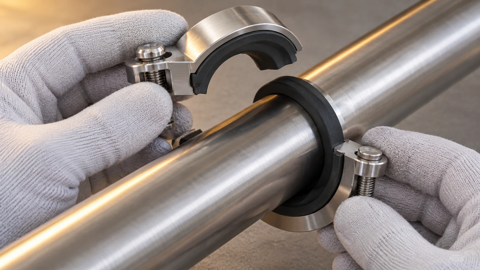
Define whether the clamp closes around the tube, supports it from below, or uses a separate retainer. Specify how fasteners are secured and how the assembly is inspected. Do not use an arbitrary torque value to create a desired compression; use the program-controlled fastener and installation procedure.
If a liner is used, consider whether it can creep, shed particles, absorb fluids, degrade under temperature, or shift during installation. Its thickness affects the final fit and may change the gap. Specify the material and installation orientation, and define how the finished assembly is checked.
Preserve thermal and contamination controls
A clamp can alter the local thermal path by conducting heat into or away from a line. If the system relies on thermal isolation or a controlled heat sink, the support material and contact area must be reviewed with thermal engineering. Surface finishes and liners can change contact conductance, so material choices should be included in the thermal analysis assumptions.
Contamination controls may influence machining, deburring, cleaning, packaging, and handling. Even if a support is not part of the wetted fluid path, chips, residues, or unapproved coatings can be unacceptable in a sensitive assembly. Identify the required cleanliness level and the approved cleaning process before selecting a manufacturing route.
Protect the line during installation and rework. The design should allow the clamp to be opened or removed without scraping the tube or requiring an uncontrolled twist. If the line is already joined into a closed circuit, the assembly sequence may dictate a split clamp or removable support.
Translate the support into controlled geometry
Define a mounting datum, tube centerline or support plane, clamp opening, contact width, fastener location, and any allowed travel. Use section views to show how the tube sits in the clamp and how the assembly is retained. If two clamp halves mate, control the interface so that a gap or offset does not create a sharp step against the line.
Manufacturing route depends on quantity, geometry, material, and precision needs. A machined block may suit a compact support with accurate mounting features; a formed part may suit a light bracket with simpler geometry. A polymer insert can be produced separately when it is an approved material. These options should be compared against cleanliness, inspection access, and the program’s approved material list.
For precision support bodies, mecanizado CNC may be evaluated against the released drawing. For relevant material discussions, use the approved system specification; the site’s aluminum alloy information is only an initial manufacturing reference and does not establish propellant compatibility.
Check the assembly under the right conditions
Dimensional inspection can establish clamp geometry and mounting location. A fit check can confirm tube seating, clearance, and access. A movement check can confirm that an intended sliding feature travels as designed. Pressure or leak testing belongs to the fluid system and must follow its approved test procedure; a clamp fit check is not evidence of line integrity.
Record line revision, clamp revision, support classification, material and finish, fastener procedure, and any permitted movement. If the assembly is tested under a representative thermal or vibration condition, document the configuration and acceptance criteria. A result from one tube route cannot automatically be transferred to a different route or support spacing.
Inspection should also consider the final line condition. Look for abrasion, deformation, coating damage, displaced liners, loose hardware, or contact with adjacent structure. The responsible team defines what is acceptable and whether any post-test inspection is required.
A clamp is part of the fluid-system load path
A reliable spacecraft propellant line clamp controls the line’s position while respecting its permitted movement, contact limits, thermal behavior, and cleanliness requirements. The design becomes easier to manufacture when the tube data, support function, datum scheme, material controls, and inspection plan are agreed before the clamp drawing is released.

