


A clutch drum spline transfers torque between a drum or hub and the component engaged with its internal teeth. The useful question is not simply whether the spline “fits.” The tooth form, bore, axis, lead, engagement length, and mating-part condition all influence assembly and load sharing. A drawing review should therefore connect the internal spline to the drum’s functional datums and identify how the fit will be verified.
For prototype development, the critical choice is often how to express the fit so that design, manufacturing, and inspection are discussing the same characteristic. A nominal tooth count or major diameter is insufficient on its own. The drawing should define the applicable spline standard or provide the required geometry, tolerance class, and inspection method. Without that information, a supplier cannot safely infer the intended backlash or engagement from an image or from another transmission part.
What the spline has to do in the assembly
An internal spline can transmit torque while allowing axial movement, hold a part at a defined position, or participate in a more constrained stack. Those functions lead to different requirements. A sliding connection may need controlled clearance and freedom over its engagement length; a locating connection may emphasize backlash, concentricity, or face position. The drum’s surrounding wall and support features also influence how the part behaves, so the spline should be reviewed in the assembly section rather than alone.
Start by identifying the mating external spline and the operating motion. Is relative axial movement expected? Which surface controls the axis? Is the drum positioned by its bore, a shoulder, a bearing, or another feature? What tooth-flank contact is intended? These questions determine which characteristics need explicit controls. They also determine whether a functional gauge, analytical measurement, or both are useful.
The literature on drum clutch hub splines notes the importance of internal diameter and gear shape to the component’s function. That is a reminder to define the inspection basis, not a reason to copy another paper’s process parameters or dimensions. Each part’s material, geometry, tooling, and required fit are specific to its design.
Establish the drum axis before defining tooth position
The bore, bearing seat, or other locating diameter typically establishes a rotational axis for the drum. The drawing should make clear whether spline position is controlled relative to that axis, an end face, or another datum reference frame. If the part includes a flange, step, or pilot, specify which surface locates the mating assembly and which surfaces are only clearance features.
For the internal spline itself, relevant attributes may include tooth count, pressure angle, module or diametral pitch, profile, lead, helix angle where applicable, tooth thickness or space width, and the fit class. Which values apply depends on the spline definition. The drawing should reference a recognized standard or supply the complete definition and tolerance. A smooth pass over a short length does not prove full engagement along the entire spline, and a single diameter cannot represent tooth-form accuracy.
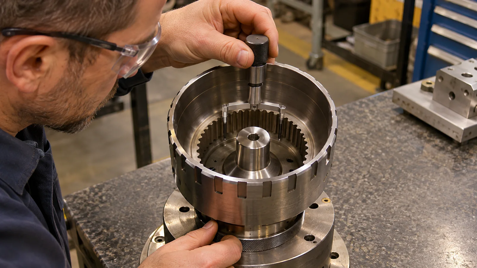
Datum transfer is particularly important when the bore and spline are produced in different operations. If the part is removed and re-fixtured, document how the bore axis and angular location are recovered. An arbitrary fixture surface may make the spline appear concentric while hiding a position error relative to the actual bearing or drum datum. That setup question should be solved in process planning, not only during final inspection.
For a related transmission component, the site’s shift fork contact-face guide discusses how contact features relate to the assembly. The shift fork performs a different role, but its fit illustrates why drawing datums should reflect the actual mating condition.
Select a production route from geometry, material, and volume
Internal splines can be produced by different routes, including broaching, shaping, hobbing for suitable geometries, forming, or other specialized methods. The feasible option depends on the spline form, through-hole or blind-hole access, material, wall thickness, production quantity, tool availability, and required quality. This article does not assume that a particular route is offered for every drum or by every supplier.
For a prototype, a design team may evaluate whether the internal feature can be made with available tooling, a modified route, or a simplified test geometry. Any simplification must be clearly marked as nonproduction and must not be used to claim final fit or durability. If a design is expected to progress to higher volume, ask early whether the prototype route preserves the functional tooth geometry needed to evaluate assembly.
Thin drum walls can distort during cutting or clamping. The workholding plan should support the part without crushing or ovalizing the bore. If heat treatment occurs before or after spline generation, the sequence must address distortion and final inspection. The engineering drawing should state whether critical dimensions are accepted in the pre-treatment or final condition.
Prototype procurement should send the drawing, mating-part model or controlled interface data, specified spline standard, material condition, and sample quantity. An incomplete interface package creates avoidable assumptions. A supplier can then identify tool or inspection questions before quoting or cutting material.
Inspect the tooth form and the functional fit separately
Inspection can combine dedicated spline gauges with analytical measurements. A go/no-go gauge answers whether a defined functional envelope is accepted under the gauge’s conditions; it does not necessarily report the individual source of an error. A coordinate or gear-measuring method may characterize profile, lead, pitch, or runout, depending on the equipment and drawing. The report should state the method and feature rather than simply mark “spline OK.”
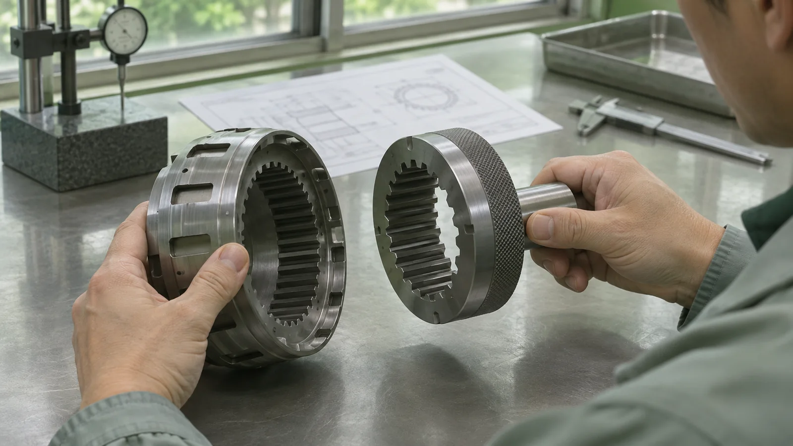
Where the drum’s bore locates the part, inspect the spline relative to that bore axis. Where the end face controls axial seating, include its relationship to the spline and any required perpendicularity or position control. If the drawing specifies backlash or a mating fit, define the mating master or reference component, engagement length, lubrication or surface condition if relevant, and how the reading is taken.
- Confirm the spline definition and tolerance source are unambiguous.
- Identify the drum axis and the feature that establishes angular orientation.
- Check whether the internal feature is through or blind and confirm full-depth access.
- Agree whether a functional gauge, analytical report, or both are required.
- Record material condition and any process step that can change tooth geometry.
For broader manufacturing context, the site’s transmission valve body guide covers a separate fluid-control component. The two parts have different acceptance logic, but both benefit from early agreement on interfaces, datum references, and inspection evidence.
Material and treatment affect the inspection plan
Material and heat treatment must follow the product specification. A spline can be made from different steels or other alloys depending on load, wear, mass, corrosion, and manufacturing needs. The supplier should not select a grade based on a generic “clutch drum” description. The drawing or purchase specification should identify the grade, condition, hardness requirement if any, and required material documentation.
Heat treatment may change size or shape; coatings and surface treatments can change effective fit. If the final mating condition occurs after treatment, inspect the functional interfaces after that step or define a validated allowance strategy. If parts are measured before a coating, clarify how coating thickness and variation are accounted for. A pre-treatment measurement cannot automatically certify a finished spline.
The alloy-steel and stainless-steel material references on the site can support early conversation, but they do not replace the specified grade or design approval. For a prototype clutch drum spline, a CNC machining capability review may be relevant when the geometry suits a subtractive process; spline-specific route feasibility still depends on geometry, tooling, and inspection requirements.
Questions that prevent avoidable fit disputes
Is tooth count enough to define an internal spline?
No. The form, pitch, pressure angle, tooth thickness or space width, tolerance class, and other geometry must be defined by a standard or complete drawing data.
Can a go gauge prove every spline characteristic?
No. It checks a functional condition defined by the gauge. Separate analytical measurements may be needed for profile, lead, position, or other specified features.
Should spline fit be checked against the customer’s mating part?
Use a controlled master or mating part only when the inspection plan defines its revision, condition, engagement, and acceptance criteria. An uncontrolled sample can create an ambiguous result.
Conclusión
A dependable clutch drum spline definition ties the tooth form and fit to a clearly established drum axis, angular reference, and mating condition. The manufacturing route should be selected from the actual geometry, material, volume, and tool access, while inspection should distinguish functional fit from individual tooth-form measurements. Those details let a prototype review answer a real assembly question instead of relying on a vague statement that the spline “fits.”
Reference
- Optimization of Manufacturing Conditions for Spline of Drum Clutch Hub Taguchi Method, 28th ISARC Proceedings.

