


A brake pedal bracket is often treated as a simple support, yet its geometry controls how the pedal rotates and how force reaches the linkage. The useful question is not how to make the part look like a bracket; it is which interfaces must remain related after machining, assembly, and inspection. A good review starts with the pivot axis, then follows the load path through the mounting faces and clevis connection.
This guide is for engineers preparing a prototype or reviewing a machined bracket drawing. It focuses on datum choices, feature relationships, material and process decisions, and inspection planning. It does not define a universal vehicle specification: the released drawing, design authority, and applicable validation plan govern every safety-related dimension.
Start with the motion that the bracket must preserve
The pivot bore or paired pivot holes establish the pedal’s rotation axis. Their location matters in relation to the vehicle mounting interface and the pushrod or clevis connection. If the drawing controls each hole independently from unrelated edges, a part can meet local dimensions while the assembled pedal still sits at an unintended angle.
For a brake pedal bracket, first identify the functional chain: mounting face, pivot axis, pedal arm clearance, and linkage connection. Ask which relationships affect motion, alignment, or interference, and which dimensions merely describe the envelope. This separates critical-to-function geometry from reference dimensions and helps prevent unnecessary tight tolerances.
Where two ears support a pivot pin, the design may call for coaxial holes, a common bore, or a specified relationship to a datum axis. The correct requirement depends on the assembly. Do not assume that a single positional tolerance captures every need: the drawing may also need to control the distance between ears, local wall thickness, or the perpendicularity of a mounting face.
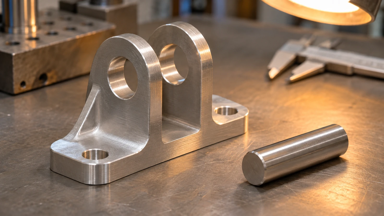
Build a datum scheme around assembly references
A practical datum plan normally begins with the surface that seats against the vehicle structure, if the drawing identifies that surface as the primary assembly reference. A second datum can locate the bracket laterally, while a third fixes the remaining direction. The pivot axis and linkage interface are then evaluated from that same frame rather than from whichever edge is easiest to touch.
Datum selection must reflect how the part is fixtured and inspected. A broad mounting surface may be a stable primary reference, but a thin or irregular casting can rock unless the drawing defines the intended contact points. If the component is machined from billet for a prototype, the stock setup may differ from a later casting process. The datum strategy should still preserve the design’s assembly logic.
For a brake pedal bracket, record the datum reference frame on the drawing and make it possible to reproduce in inspection. If the assembly uses a pin, mating plate, or fastener pattern as a functional reference, a representative fixture can help, but its status must be documented. A fixture is not a substitute for defining the part’s actual acceptance criteria.
Choose the manufacturing route from the feature set
Prototype brackets can be machined from a suitable metal stock when the design and material specification allow it. CNC milling can establish mounting faces, holes, slots, and local profiles in a controlled sequence. The selected route depends on geometry, stock availability, required quantity, surface condition, and whether the prototype is intended for fit checks, functional tests, or another limited purpose.
Machining sequence matters. A stable reference face is often created first; subsequent setups use it to locate the pivot features and mounting pattern. If the bracket has deep pockets or thin arms, removing material can release stress or reduce rigidity. Leaving temporary support stock, changing the order of cuts, or splitting operations across setups may help, but those decisions must be based on the actual geometry and material condition.
For a brake pedal bracket with opposed ears, consider tool access and the ability to maintain the same axis across the holes. Depending on geometry, a common setup, a suitable boring operation, or a dedicated fixture may be considered. These are planning options, not promises that one process is required or available for every part. A supplier reviewing a model should flag inaccessible features and ask the designer to confirm which surfaces are functional.
Specify material and finish without guessing
Material choice should follow the design requirement, not an assumed automotive convention. A drawing may specify a particular aluminum alloy, steel grade, temper, heat treatment, coating, or other condition. Similar-looking stock can behave differently during machining, finishing, and service. If the specification is incomplete, resolve the grade and condition before quoting or cutting material.
Finish requirements also need context. A mounting face, pivot bore, or pin-contact surface may need different treatment from a nonfunctional exterior. If a coating is applied after machining, its thickness can affect fits and clearances. The drawing should say which dimensions apply before or after finishing and identify any masking requirements. Do not infer that a cosmetic finish is suitable for a bearing or sliding interface.
When reviewing a brake pedal bracket, list the material, condition, finish, and any post-process requirements beside the critical features. If those details are unknown, record them as open questions. A prototype used for packaging review should not be represented as validated for road use unless the responsible organization has completed the required engineering and regulatory work.
Plan inspection around relationships, not a pile of dimensions
Inspection should establish the datum frame, measure the mounting pattern, and verify the pivot axis and linkage connection against the drawing. A caliper can check accessible sizes, but it cannot by itself establish coaxiality, position, or orientation. Depending on the specified characteristics, a coordinate measuring machine, dedicated fixture, pin gauges, or other method may be appropriate; the method must suit the tolerance and the inspection plan.
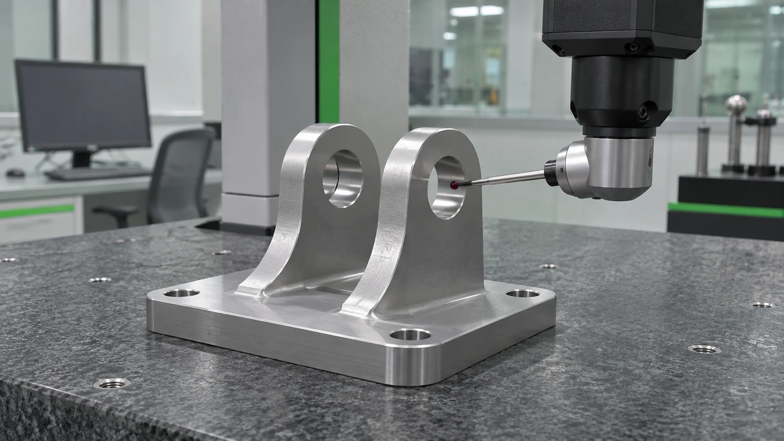
For a brake pedal bracket, ask the supplier to report the critical features in a way that identifies the datum setup and measurement method. If a representative pin or mating plate is used, identify its calibration or status and explain what relationship it verifies. A functional check can supplement dimensional inspection, but it should not replace measurements when the drawing requires them.
Revision control is part of inspection. Record the drawing revision, material certification or traceability documents requested by the customer, inspection equipment used, and any approved deviations. If a feature changes after a prototype review, ensure the next inspection plan follows the released revision rather than an obsolete model.
What to send for a useful prototype review
Provide a released drawing or clearly controlled model, the material and condition, the intended quantity, critical-to-function features, finish requirements, and the expected inspection deliverables. Mark the assembly references and explain whether the prototype is for envelope, fit, motion, or a limited functional evaluation. Those distinctions help a supplier identify questions before machining begins.
For related manufacturing context, see the site’s CNC machining capabilities. The page describes the service scope; the part drawing still determines whether a specific bracket geometry, material, or inspection requirement can be supported.
A useful brake pedal bracket review ends with a short, explicit list: confirmed datums, critical relationships, unresolved specifications, planned inspection evidence, and any features that need design clarification. That list is more valuable than simply labeling the component “precision machined.” It connects the part’s motion to measurable requirements while keeping safety and validation decisions with the responsible design organization.
Worked review scenario: the pin fits, but the pedal angle is wrong
Hypothetical engineering scenario, not a Jucheng customer case: a prototype pedal bracket accepts its pivot pin, and every checked hole diameter is within the drawing limits. After assembly, however, the pedal rests at an unexpected angle and the clevis does not line up cleanly with the linkage. Reaming the holes may seem like the fastest fix, but it would address a symptom before identifying the controlling relationship.
The review should first recreate the assembly datum frame. Check whether the pivot axis was measured relative to the mounting face and locating pattern, or whether each feature was reported independently from convenient stock edges. Then inspect the mounting face seating condition, the spacing between the ears, and the clevis interface against the same reference. If the pivot holes are individually acceptable but their common axis is not controlled, the drawing may not yet define the assembly relationship the team needs.
Next separate a part issue from a fixture or mating-part issue. Confirm the assembly plate revision, pin condition, fastener seating, and intended orientation. If the part is the source, decide which characteristic explains the angular error: axis position, face orientation, ear spacing, or another specified relationship. Revise only the control that expresses the function. Tightening every dimension can increase cost while leaving the underlying datum ambiguity untouched.
The revised inspection plan should state how the mounting face is seated, how the pivot axis is established, and which clevis or linkage feature is checked from that frame. This turns a vague “pedal sits crooked” observation into evidence that can guide a drawing change or process correction without implying that an unvalidated prototype is safe for vehicle use.
FAQ: brake pedal bracket drawing and inspection
Which feature should establish the primary datum?
Use the feature the design identifies as the main assembly reference, often a mounting surface or a defined locating interface. The drawing owner should confirm the choice against the actual installation. A convenient machining surface is not automatically a functional datum.
Do paired pivot holes always need a common axis control?
Only when the design and assembly require a shared pin axis. If the holes work as a pair, the drawing should define their relationship using an appropriate geometric control and datum frame. The required tolerance comes from the design, not a generic bracket rule.
Can a prototype fit check prove the bracket is ready for road use?
No. A fit check answers only the stated assembly question. Vehicle use requires the responsible organization’s engineering validation, safety review, and any applicable compliance work; a machined prototype does not provide that evidence by itself.
What information helps a supplier review the part before machining?
Send the controlled drawing and model, material grade and condition, finish requirements, quantity, critical interfaces, intended evaluation, and inspection deliverables. Mark the mounting reference and explain whether the sample is for envelope, fit, motion, or another limited purpose.

