


An aircraft actuator is a motion-producing assembly, but the manufacturing request usually concerns one defined part inside that assembly: a housing, piston, shaft, rod end, clevis, port block or mounting feature. Treating the whole actuator as one generic precision part hides the interfaces that determine whether components fit, move and can be inspected. A supplier-ready package begins by separating the assembly function from the part-level scope.
This article is for engineers and buyers planning a new component, prototype or build-to-print order. It does not prescribe actuator design, repair, aircraft installation or system qualification. Released engineering data and the responsible program authority control those decisions.
- Start with the actuator job and quoted boundary
- Map load and motion interfaces
- Keep fluid, electrical and mechanical features distinct
- Choose operations around the part family
- Design inspection around hidden features
- Make the RFQ package answerable
- Frequently asked questions
Start with the actuator job and quoted boundary
An actuator converts an input – often hydraulic, pneumatic or electrical – into controlled movement. The assembly may include a body, moving element, seals, bearings, fittings, sensors and control electronics. The exact architecture varies. Before asking a manufacturer to quote, state whether the scope is one machined component, a set of components, an assembly operation or a prototype intended for fit evaluation.
That boundary changes the required information. A housing-only RFQ needs port geometry, mounting interfaces, sealing surfaces and inspection requirements. A shaft or rod request may need end features, bearing seats, thread details and surface condition. An assembly quote also needs the bill of material, supplier-furnished items, assembly sequence and acceptance evidence. Without a declared boundary, quotes can look comparable while including different work.
Manufacturing-focused supplier pages commonly describe actuator subcomponents such as housings, pistons, shafts and fittings; Miller CNC, for example, discusses housing machining with turning and multi-axis milling. That is a process reference, not proof that every actuator architecture uses the same construction or that one supplier scope applies to another program.
Map the load and motion interfaces
Begin with a simple interface map. Identify where force enters and exits, how the part locates in the assembly, what features constrain rotation or translation, and which surfaces contact a seal, bearing or guide. A housing can have several distinct coordinate systems: external mounting datums, a cylinder bore, port axes and sensor openings. The drawing should make their relationships explicit.
Long shafts and rods bring their own handoff questions. The drawing may need to control straightness, concentricity, bearing-seat relationships, thread runout or a specified finish. Those requirements should follow the approved design and the way the part is accepted; they should not be guessed from a general aircraft-quality label.
| Part family | Interface to clarify | Manufacturing question |
|---|---|---|
| Housing or cylinder body | Bore axis to mounting faces and port axes | Can the relationships be held through planned setups? |
| Piston or spool | Sliding surface, grooves and end features | How will size and finish be verified without damage? |
| Rod or shaft | Bearing seats, threads, flats and end connections | Where is support needed to control cutting deflection? |
| Clevis or rod end | Pin bore, centerline and attachment face | Does the datum scheme reflect assembly location? |
A useful review compares the part drawing with the assembly model or controlled interface drawing. It does not authorize changing the design. If the model and drawing disagree, record the discrepancy and route it to the responsible design authority before production programming proceeds.
Keep fluid, electrical and mechanical features distinct
Actuator housings may carry pressure ports, passages, seal glands or sensor pockets. Those features are not interchangeable with ordinary clearance holes. The drawing should identify port standards and thread forms, seal contact requirements, passage intersections, plugs and any cleanliness or inspection expectations that apply to the project. The manufacturing team should not infer a pressure boundary or fluid compatibility requirement from the word actuator.
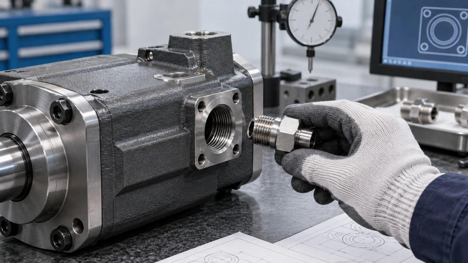
Cross-drilled passages can create a planning problem: a feature may be easy to machine but difficult to deburr or inspect after it intersects another passage. A manufacturability review should ask whether the tool can reach each intersection, how chips and burrs will be removed, and what evidence confirms the finished condition. If the design requires a test or cleanliness verification, specify who performs it and what record is delivered.
Electrical variants add connector openings, wire routing, sensor mounting and sometimes a separate electronics enclosure. Keep those functions visible in the bill of material and drawing set. Do not let an electrical cutout silently move a load-bearing wall or conflict with a seal land during revision changes.
Choose manufacturing operations around the part family
Turning, milling, drilling, boring, grinding, finishing or additive manufacturing may appear in an actuator component route, depending on material, geometry, quantity and product stage. The right question is not which process is best for actuators. It is which route can make this released feature set repeatably and leave the required characteristics accessible for inspection.
For a housing with coaxial bores and external mounting features, setup sequence can affect the relationship between bore and datum face. For a slender rod, support and clamping can influence deflection. For a small port block, tool access and deburring may dominate the plan. Each component calls for its own process review, even when all parts belong to one actuator assembly.
Prototype and production plans can differ. A prototype may answer packaging or interface questions; it is not automatically a qualified flight part. For broader process context, the Aviation & Aerospace manufacturing and prototyping page describes the project-level landscape. The actual route must still be tied to the released drawing and approved scope.
Design inspection around hidden or functional features
Inspection planning should start with characteristics that affect fit, movement or the specified boundary – not a generic checklist. Decide how the bore, port position, pin axis, thread, seal surface or shaft diameter will be measured. Consider whether a probe, gauge, optical method or other approved approach can reach the feature in its finished condition.

For hidden passages, surface condition and cleanliness may matter as much as opening dimensions. The acceptance plan should state whether the requirement is visual, dimensional, flow-related or another defined check. Do not imply that a visual inspection proves an internal passage is free of every defect, or that a component-level report proves the assembled actuator performance.
Traceability connects the measured part to its drawing revision and material condition. If heat treatment, coating or another controlled process occurs between machining steps, identify which dimensions are checked before or after that operation. A measurement record without the right revision and sequence context can be difficult to use at receiving.
Make the RFQ package answerable
A strong RFQ gives the supplier enough information to quote the same scope the buyer intends to purchase. Include the released drawing and model, material and condition, quantity and lot expectations, finish and special-process requirements, inspection records, packaging, revision status and delivery milestones. If a requirement is not yet known, mark it as open rather than leaving suppliers to make different assumptions.
- Identify the exact part and current drawing/model revision.
- State whether the quote covers a component, matched set or assembly.
- List functional datums, critical interfaces and source-controlled features.
- Specify material, condition, finish and traceability documents.
- Define inspection records and tests included in acceptance.
- Separate prototype learning objectives from production release criteria.
Ask the supplier to identify risks before production: inaccessible features, thin walls, long reach, cross-hole cleanup, tolerance relationships and inspection limits. The objective is not to transfer design responsibility; it is to make manufacturing assumptions visible while there is still time to resolve them.
Frequently asked questions
Does an actuator housing quote include the complete actuator?
No. A housing quote may cover only the machined body and specified finishing or inspection. Seals, pistons, electronics, assembly, functional tests and qualification are separate unless the purchase scope explicitly includes them.
Can a prototype actuator component prove flight readiness?
A prototype can answer a defined question such as packaging, interface fit or a manufacturing concept. It does not establish airworthiness, system performance or qualification unless the approved program plan assigns and completes those verifications.
Which dimensions should be highlighted on the drawing?
Highlight features that control locating, motion, sealing, attachment or another stated function. The design authority must assign actual limits and datums; a supplier can review manufacturability but should not invent acceptance tolerances.
Practical takeaway: an actuator becomes quotable when the buyer defines the component boundary, maps the interfaces, names the inspection evidence and distinguishes part manufacture from assembly-level or aircraft-level acceptance.

