


A wing stringer clip connects a skin or panel to a longitudinal stiffener, transferring load through a small interface that can be easy to under-specify. The clip’s job depends on its shape, fastener pattern, edge distances, contact with the adjoining parts, and the assembly’s load path. A part that is dimensionally close can still create a poor fit if its bend, flange, or hole pattern does not match the aircraft structure.
Aircraft wing stringer clip design should begin with the controlled structural detail and the mating geometry. The responsible aircraft engineer defines the load cases and allowable joint behavior. Manufacturing planning then translates that definition into formed or machined features that can be made, inspected, and assembled consistently.
Contents
- Understand what the clip connects
- Follow load through the fastener group
- Make bend and hole geometry agree
- Control contact without forcing the structure
- Choose between formed and machined routes
- Inspect the finished joint features
- Release a traceable manufacturing package
Understand what the clip connects
Identify the stringer profile, adjoining skin or panel, clip orientation, and any nearby ribs, frames, access panels, or systems. Confirm whether the clip is a single-angle, formed channel, or more complex fitting, and which surfaces contact the adjoining structure. A two-dimensional section may not show all the installation constraints, so review the assembly model and local drawing set together.
Clarify whether the clip is intended to transfer shear, restraint, local bearing, or a combination of functions. The structural authority should specify the load path and critical characteristics. Avoid inferring a structural role from a familiar shape or from a similar part on another aircraft.
Also identify the approved part configuration and revision. If the clip is part of a controlled repair or production package, substitution of material, temper, finish, or fastener type requires the responsible approval path. The aerospace manufacturing overview provides general context, not airworthiness approval.
Follow load through the fastener group
Look at the fastener group as a system. Load enters through the clip flange, passes through fasteners and bearing surfaces, and reaches the stringer and skin. Hole spacing, edge distance, flange width, and local thickness affect that path. The approved structural analysis defines margins and allowable damage or repair conditions.
Do not optimize fastener count or diameter from a generic chart outside the governing design basis. Check the specified fastener schedule, hole preparation, countersink or head style, and any installation access requirements. A clip may look symmetric but have an orientation-specific hole pattern or load direction.
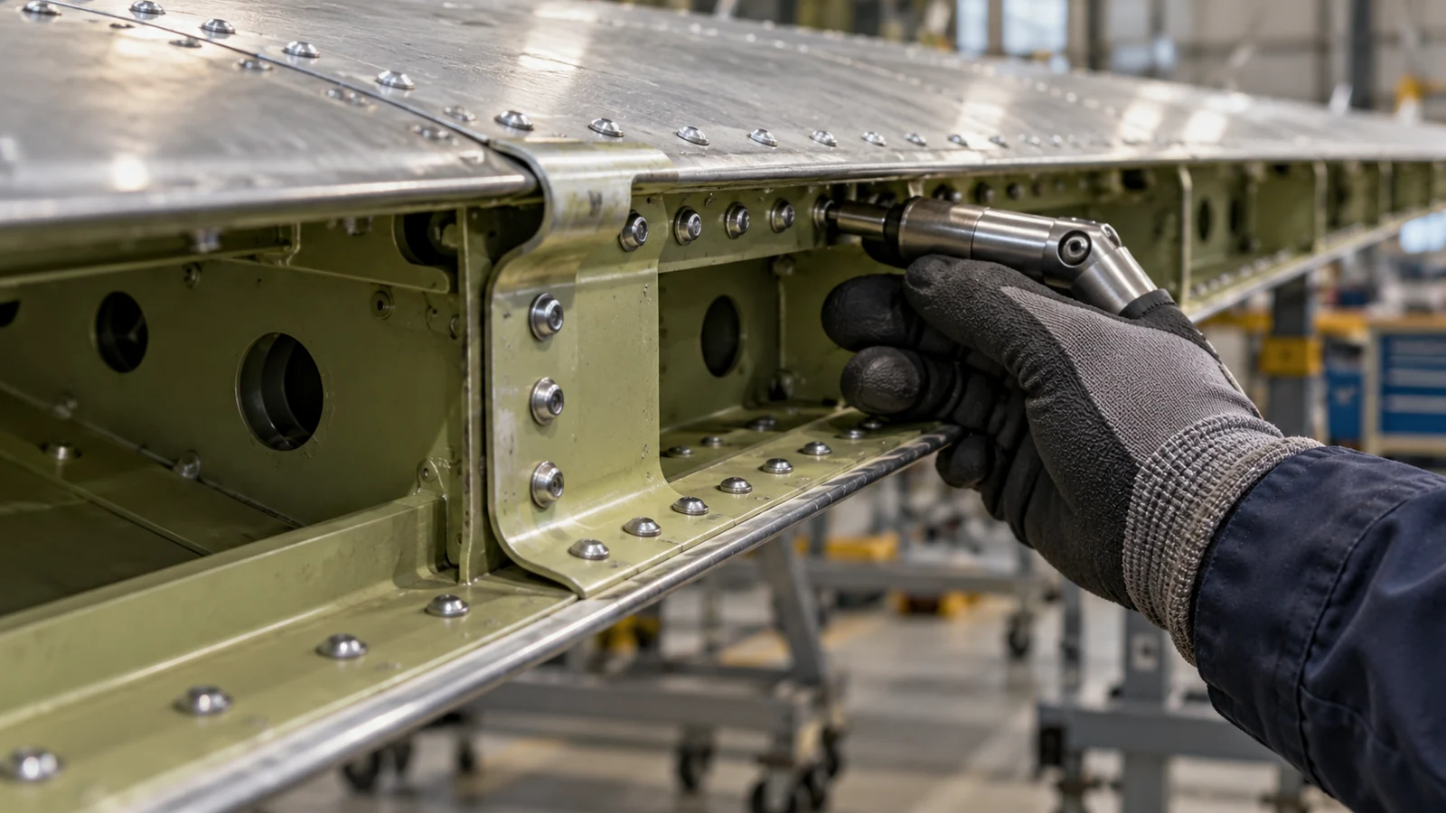
Features close to a bend can experience combined effects from forming strain, fastener bearing, and local geometry. The structural drawing should define the relevant relationship. Manufacturing feedback can flag a difficult bend or tool access issue, but any change to fastener location or flange size needs engineering disposition.
Make bend and hole geometry agree
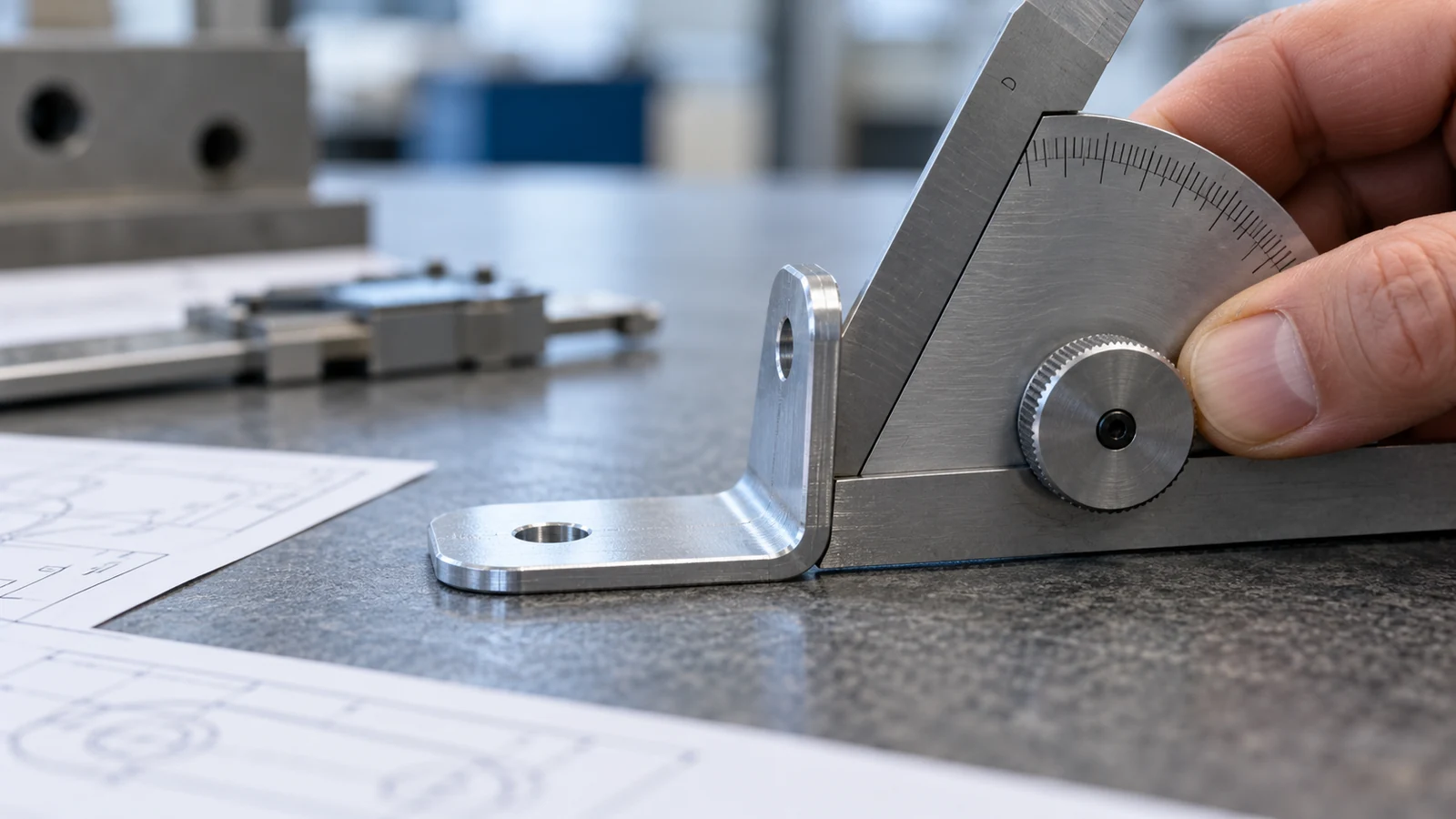
For formed clips, material thickness, temper, bend radius, grain direction, tooling, and springback influence the final geometry. Holes near a bend may distort or move relative to the flange. The drawing should specify the bend and hole relationship clearly and identify any features that must be completed after forming.
For machined clips, stock removal and thin sections can create distortion or unnecessary mass. Tool access may limit internal radii or corner details. A hybrid route may combine a formed angle with a machined interface block when the design permits, but each added joint brings new alignment and inspection needs.
Clarify whether dimensions apply before or after finishing and whether the part is measured free-state. Coatings, conversion treatments, or paint can affect fit, fastener interfaces, and corrosion protection. The approved material and finish specification controls; do not assume a generic aerospace finish.
Control contact without forcing the structure
The clip should sit against the stringer and skin as intended without requiring force that distorts the joint. A gap can indicate a bend-angle issue, a mismatch in the mating geometry, or an assembly condition that needs engineering review. Do not use fastener tightening to pull a visibly mismatched clip into position unless the approved procedure explicitly allows it.
Check the installation sequence and tool access. A flange may be hidden after a neighboring panel is installed. Confirm that fasteners can be inserted, held, and inspected in the specified order. If the clip is installed in a constrained area, a physical fit check can reveal access problems that a flat pattern or isolated part inspection will not show.
Where the joint includes sealant, shims, or surface preparation, the relevant process must be controlled separately. The clip drawing should identify the interface conditions it relies on and reference the approved assembly instruction rather than carrying improvised notes.
Choose between formed and machined routes
Sheet-metal forming is often suitable for angle or channel clips with relatively thin, uniform sections. CNC machining may suit a thick fitting, stepped surfaces, or a geometry with precise local interfaces. The best route depends on the released design, quantity, material condition, finish, and inspection needs.
| Route | Potential advantage | Review before selection |
|---|---|---|
| Formed sheet metal | Efficient material use for simple flanges and bends | Springback, bend radius, grain direction, hole distortion |
| CNC-machined fitting | Direct control of complex faces and local features | Stock waste, thin-wall stability, tool access, datum transfer |
| Hybrid construction | Combines formed structure with precision interfaces | Joint design, added fasteners, alignment, assembly records |
Jucheng’s CNC machining service can be considered for the machined route when the material and drawing support it. The choice between routes should follow engineering and procurement review, not a process preference in isolation.
Inspect the finished joint features
Inspect characteristics that establish fit and load transfer: flange angle, hole locations, contact surfaces, thickness, bend condition, edge quality, and finish. Use datums that reflect how the clip locates in the assembly. If the clip is compliant or thin, define the support condition used for measurement.
First-article inspection should report the actual results for designated characteristics and connect them to the drawing revision. A visual check can identify cracks, burrs, or obvious damage but is not a substitute for dimensional verification. The applicable structural or quality plan determines the acceptance method and sampling.
For a fit check, use the intended mating parts or a controlled fixture. Record whether the test included sealant, shims, fasteners, or adjacent panels. A successful fit on a simplified fixture does not establish airframe performance or repair approval.
Release a traceable manufacturing package
- Current drawing, model, part revision, and approved change status.
- Material, temper, grain-direction, and finish requirements.
- Fastener pattern and the controlled assembly procedure reference.
- Critical bend, hole, edge, and contact characteristics.
- Inspection datum scheme, free-state or restraint condition, and report needs.
- Quantity, production or prototype status, traceability, and packaging.
A wing stringer clip is small, but its geometry belongs to a larger structural joint. Clear load-path intent, bend and hole control, assembly access, and traceable inspection help keep the manufacturing part aligned with the approved aircraft design.

