


An aircraft control horn converts motion from a linkage into rotation or translation at a control surface. Its hole pattern and lever geometry therefore form part of a controlled kinematic chain. A machined horn that fits the hinge line but places the linkage hole incorrectly can change travel, mechanical advantage, clearance, and load distribution.
The design authority defines the control-system geometry and allowable loads. Manufacturing’s role is to preserve the released relationships and provide inspection evidence for the features that matter. This review guide focuses on the machined component: how to relate the pivot, linkage holes, attachment face, and local geometry in a drawing and process plan.
Contents
- Start with the linkage geometry
- Make the pivot and attachment interface explicit
- Control hole relationships, not just diameters
- Keep load-bearing geometry tied to analysis
- Plan machining around critical features
- Inspect the completed kinematic chain
Start with the linkage geometry
Identify the control-surface hinge axis, horn pivot or attachment reference, linkage direction, and permitted range of movement. The location of each hole relative to the pivot determines the lever arm. The angular position of the horn and the linkage’s line of action affect travel and mechanical advantage. These values come from the approved control-system design and should be represented in the controlled model.
Review the complete motion envelope, not only the neutral position. Check clearance between the horn, linkage end, adjacent structure, fairings, and any stops through the full specified travel. A hole pattern that is correct at one position may still cause interference or an undesirable linkage angle elsewhere.
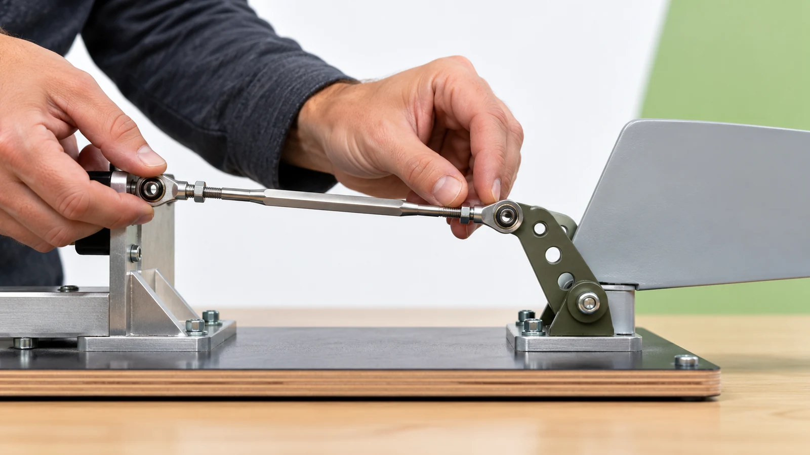
Do not redesign the lever arm to solve a packaging issue without the responsible system authority. A small geometric change can affect the control response. Manufacturing can identify a machining or access concern and propose options, but the approved kinematics remain the baseline.
Make the pivot and attachment interface explicit
A control horn may attach to a shaft, a control surface, a bracket, or a combination of features. State which bore, face, spline, keyway, or fastener pattern establishes location and torque transfer. If the horn’s angular orientation is critical, provide an indexing feature or a clear datum reference rather than relying on visual alignment.
Consider whether the attachment is slip-fit, press-fit, clamped, keyed, or otherwise retained. The design authority defines the fit and assembly method based on loads, material, and service strategy. The drawing should distinguish a locating fit from clearance for a fastener or pin.
Specify surface finish and edge condition where they affect a bearing, bushing, or fatigue-sensitive transition. A cosmetic edge break may not be appropriate at a controlled contact face. Keep general deburring notes separate from functional edge requirements.
Control hole relationships, not just diameters
Linkage pin holes often need more than a diameter tolerance. Their position relative to the pivot, their orientation through the horn, and their relationship to the control surface determine the assembly geometry. Define the datums and geometric controls that express those relationships. If a bushing or bearing is installed later, state whether dimensions apply before or after installation.
Review edge distance, ligament width, countersink or chamfer, and access for pin retention. These features are part of the approved structural design. Do not infer safe edge distances or fastener sizing from generic examples; refer to the controlling drawing and analysis.
If several holes provide alternate rigging positions, identify each position clearly and define which one is used for the released configuration. A manufacturing inspection should report their actual locations relative to the pivot datum, not simply state that every hole is within size limits.
Keep load-bearing geometry tied to analysis
Control horns can experience cyclic loading and local stress around holes, fillets, and transitions. The structural analysis determines load cases, material, fatigue considerations, and allowable geometry. Changes to the hole size, edge distance, thickness, or fillet can invalidate an evaluated configuration even if the part still looks similar.
Machining marks, burrs, and sharp transitions may matter at fatigue-sensitive locations. Identify surfaces or edges that require special finishing and inspection. If a polishing or blending operation is permitted, define its boundary and acceptance method so that it does not remove material unpredictably.
Material condition and orientation can also be controlled inputs. The approved specification defines alloy, temper, traceability, and any heat treatment. The supplier should not substitute a convenient grade because it is easier to machine.
Plan machining around critical features
A machined control horn may be cut from plate or billet, depending on geometry and the released design. Workholding should support the part without distorting thin arms or locally stressing a hub. If the pivot bore and linkage holes are machined in separate setups, the datum transfer must preserve their relationship.
Consider tool access to the bore, slot, and internal corner radii. Long-reach tools can deflect; small radii can limit cutter selection; thin webs may move as material is removed. Process planning should account for the finishing sequence and whether a post-process operation changes the final position or surface state.
Jucheng’s CNC machining capability can be evaluated for the released part, material, tolerances, and inspection package. The aluminum alloy material overview may support an early machinability discussion, but it does not replace the aircraft’s approved material specification.
Inspect the completed kinematic chain
Inspection should confirm the pivot datum, linkage-hole positions, attachment interface, thickness, and any controlled bearing features. A CMM or other suitable method can evaluate position, but the setup must reflect how the horn is located in the assembly. If the part is measured in a fixture, record the fixture and support condition.
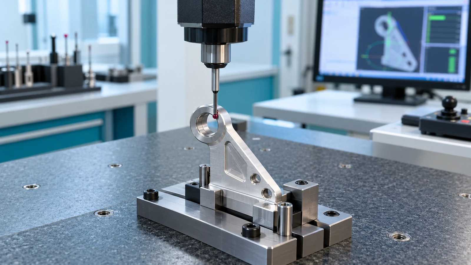
After finishing or bushing installation, re-check characteristics that may have changed. Keep first-article records linked to the part revision and material traceability. If a deviation affects a functional hole or pivot relationship, obtain design-authority disposition rather than accepting it based on a fit check alone.
Assembly verification can then confirm rigging, clearance, and travel using the approved procedure. Dimensional inspection of the horn and system-level control checks answer different questions. A component report should not be presented as proof of aircraft-level control performance.
Preserve the lever geometry through manufacture
Aircraft control horn machining is successful when the pivot, linkage holes, attachment interface, and load-bearing profile remain tied to the approved control-system definition. Clear datums, stable setups, controlled material, and a verification plan focused on the kinematic relationships make the part easier to quote, inspect, and integrate without asking manufacturing to infer flight-control design intent.

