


An aircraft door frame is judged by an opening that remains usable after forming, joining, finishing, and installation. A frame can match its nominal profile on a flat inspection table yet create uneven gaps or difficult fit-up once it meets the surrounding fuselage structure. That is why the part should be planned from the opening and its interfaces outward, not treated as a sheet-metal outline whose dimensions can be checked one at a time.
For design and sourcing teams, the important manufacturing question is how the frame will retain its shape through the complete route. The discussion below connects geometry, material condition, forming strategy, joining, and inspection to practical aerospace prototyping and manufacturing. It does not replace aircraft-specific design approval or structural substantiation.
Contents
- Treat the door opening as the controlling interface
- Read the frame as a formed structure
- Choose sheet stock with the forming route in mind
- Sequence forming, trimming, and joining
- Protect fit-up through inspection planning
- What a first article should teach the team
- Release information that prevents interpretation gaps
- Practical questions before ordering
Treat the door opening as the controlling interface
Start with the installed condition. Identify the adjacent skin, reinforcement, hinge or latch features, seal contact, trim boundaries, and any structure that locates the frame. Then establish which surfaces and datums govern the opening. The nominal perimeter is not enough: the design may depend on local flange position, corner radii, fastener alignment, or the relationship between the opening and a mating door.
A useful drawing review separates functional dimensions from reference geometry. For example, a broad formed contour may be allowed to vary within a defined profile zone while a latch-side interface requires tighter positional control. If every edge is given the same tolerance, the drawing can become expensive to inspect without improving the fit that matters. Conversely, an undefined corner transition can become a supplier interpretation that changes the seal path.
Record the assembly sequence as well. Is the frame installed before or after adjacent panels? Does it locate itself from a fixture, fasteners, or the surrounding structure? A frame that is pulled into position by fasteners may show different behavior from one expected to sit naturally against a datum surface. That affects both manufacturing fixtures and acceptance criteria.
Read the frame as a formed structure
Door frames often combine a curved perimeter with flanges, returns, local joggles, and cutouts. Each change in section affects how the sheet stretches and springs back. Tight radii can concentrate strain; long flanges can twist; asymmetric features can move the neutral shape. A flat pattern may describe the starting blank, but the finished geometry depends on material, thickness, bend sequence, tooling, and restraint.
Inspect the corners deliberately. They are where multiple bends, relief cuts, seams, and local reinforcements may converge. A relief that prevents tearing can also leave an opening or edge condition that needs closure or finishing. A corner designed for a sharp visual boundary may be difficult to form consistently without a dedicated tool or secondary operation. These tradeoffs should be resolved in design review rather than discovered after the first formed part.
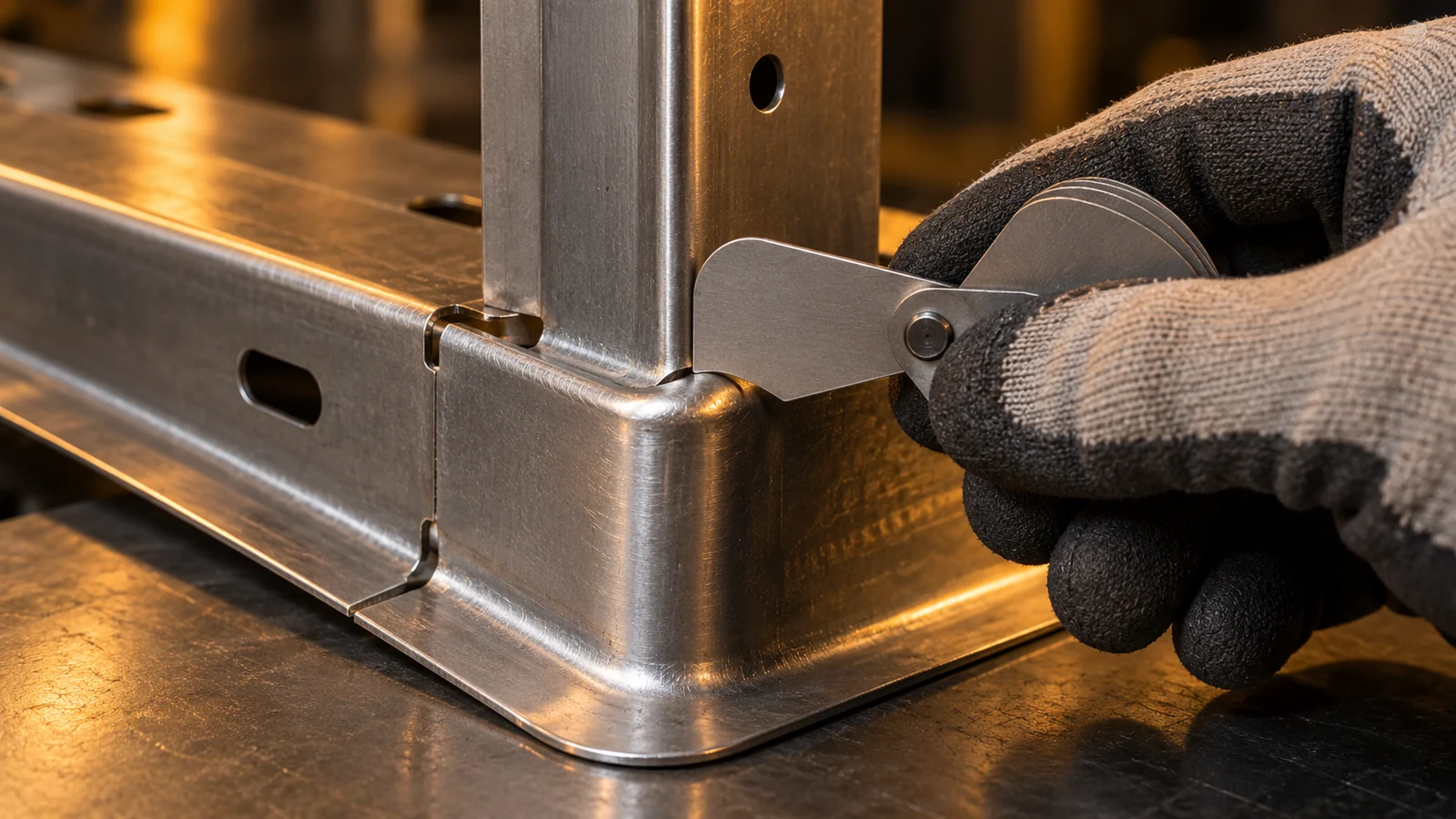
Do not assume that a larger forming tool automatically solves springback. Springback depends on material behavior and geometry as well as tooling. The production route may require compensation, staged forming, restrike, or controlled fixturing. Those are process decisions to be validated against the released requirement. A supplier should not silently alter the nominal model to make the part easier to form; compensation belongs in the manufacturing method, with approved drawing changes when the product definition itself changes.
Choose sheet stock with the forming route in mind
Material selection is not a standalone strength comparison. The team must consider alloy and temper, sheet thickness, directionality, bend radius, corrosion exposure, joining method, finish, and the structural role of the frame. A material condition that meets strength requirements may have different formability from one selected for easier shaping. The responsible design authority determines which tradeoff is acceptable.
| Choice to resolve | Manufacturing consequence | Drawing or sourcing detail |
|---|---|---|
| Alloy and temper | Influences formability, strength, and springback | Exact specification and condition |
| Thickness and bend radius | Affects strain, corner behavior, and tool access | Nominal thickness and defined minimum radii |
| Grain direction | Can affect bend consistency and crack risk | Blank orientation where functionally required |
| Finish and protection | May change handling, joining, and surface condition | Finish sequence and areas to mask or protect |
For early iterations, distinguish fit-check stock from material intended to represent a structural build. A rapid prototype can answer whether the opening clears neighboring parts or whether the flange layout is workable, but its material and process may not represent final strength, fatigue, or environmental behavior. The aerospace materials guide is a starting point for comparing material questions, not an approval list for a particular aircraft structure.
Sequence forming, trimming, and joining
A manufacturing plan should identify when the part is formed, when the perimeter is trimmed, and when holes and joining features are added. Trimming too early can remove material needed to control the part during forming. Trimming too late can make tool access difficult. The best sequence depends on the frame geometry and available inspection references, so it should be reviewed against the actual drawing rather than selected by a generic rule.
Where several segments or reinforcements are joined, define how the assembly is located. A fixture can hold the opening perimeter, but excessive restraint may conceal distortion until the part is released. The plan should state which surfaces are clamped, where the datum references are, and whether the acceptance check occurs in a free state or a specified restrained condition. Without that distinction, two measurements can disagree while both appear reasonable.
Joining also changes the frame. Heat input, fastener installation, and local stack-up can affect alignment. If the frame is delivered as a subassembly, inspect the assembled opening and critical interfaces, not only the individual formed pieces. A concise sheet-metal fabrication route can connect blank preparation, forming, trimming, joining, and finish protection into one reviewable sequence.
Protect fit-up through inspection planning
Inspection should reproduce the functional question. If the concern is the opening profile, the method must evaluate that profile relative to the chosen datums. If the concern is a hinge or latch pattern, confirm the pattern’s location from the same references used in assembly. A tape measure around the perimeter cannot establish those relationships, and isolated dimensions may miss a gradual twist.

Choose a measurement approach appropriate to size and geometry. A dedicated checking fixture may be useful for repeat builds; coordinate measurement or optical methods may suit development work; templates can provide a quick local check when their limits are understood. The drawing or inspection plan must define the acceptance method and conditions. Do not infer aircraft acceptance limits from general manufacturing practice.
Include edges, burrs, and surface protection in the plan. Door openings interact with seals, covers, and people handling the assembly; a sharp edge or damaged coating can create issues even when the overall profile is acceptable. Document where masking is required and when protective films are removed. If inspection is performed before finishing, specify which characteristics must be rechecked afterward because coating or joining can alter them.
What a first article should teach the team
The first formed frame should answer a small number of explicit questions: Does the forming sequence create the required perimeter? Which areas show the greatest springback? Can the assembly fixture locate the opening without forcing it? Are the critical features accessible to inspection? How much adjustment remains between the design and the manufacturing route?
Capture the answers with the part revision, material lot or documentation, process sequence, fixture reference, and measurement method. If a local flange is adjusted, record whether the change affected neighboring holes or seal surfaces. A prototype is more valuable when it reveals cause and effect, not just a list of dimensions that passed or failed.
For a changing design, consider splitting learning into stages. A simple formed sample can reveal bend behavior; a complete frame can test opening fit and assembly; a later representative build can address the program’s specific verification requirements. Avoid calling an early fit-check flight ready or using it as evidence for performance it was not designed to test.
Release information that prevents interpretation gaps
A clear supplier package includes the controlled drawing and model, revision status, material specification and condition, grain-direction notes where needed, datum scheme, profile controls, edge requirements, finish sequence, and inspection expectations. Identify the authority for deviations and clarify whether the drawing, model, or a separate specification governs any conflict.
Ask the supplier to flag high-risk bends, corner details, unsupported free-state conditions, and inaccessible inspection features before making tooling or fixtures. These questions are easier to resolve before the blank is cut. When revisions occur, provide a change summary that identifies the affected interfaces rather than sending a replacement file without context.
The practical goal is a door frame that can be formed and evaluated in a way consistent with its installed function. When opening datums, material condition, forming sequence, joining restraint, and inspection all refer to the same design intent, the team can make progress without treating every fit problem as a last-minute adjustment.
Practical questions before ordering
Should the frame be inspected in a fixture?
Only if the drawing or approved inspection plan defines that condition. The team should distinguish a free-state profile check from a restrained assembly check so the fixture does not hide distortion.
Can a prototype use a different alloy?
It may be suitable for a limited fit or packaging question, but the difference must be documented. A substitute material does not demonstrate the final part’s structural or environmental performance.
When should corner reliefs be finalized?
Before the first representative forming build. Relief geometry affects strain, edge condition, joining, and inspection, so it should be reviewed as part of the frame rather than added as an undocumented shop adjustment.

