


Automotive plastic parts are not simply metal parts remade in polymer. They combine geometry, material behavior, tooling strategy, joining features, appearance requirements, and vehicle-life exposure in one decision. A successful part begins with the load case and operating environment, then moves to resin selection and manufacturing—not the other way around.
This guide gives design and sourcing teams a practical framework for choosing how an automotive plastic component should be made, what must be specified on the drawing, and which risks deserve prototype testing before production tooling is released.
Contents
The Part’s Job Defines the Engineering Route
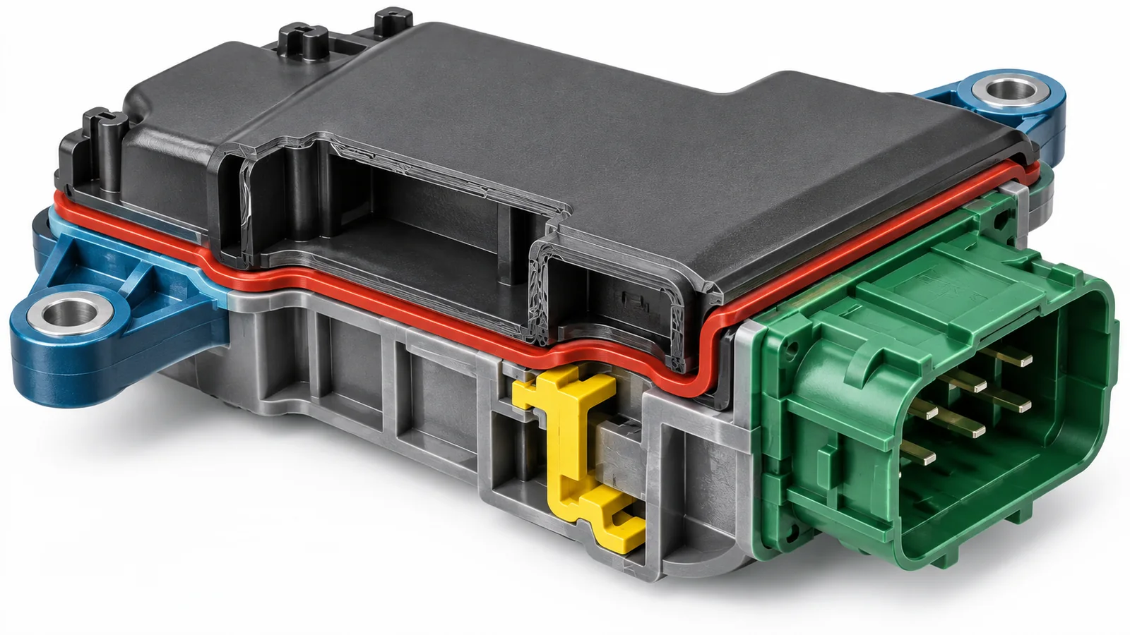
A trim bezel, battery connector housing, under-hood duct, sensor cover, fluid reservoir, and structural seat component may all be called plastic parts, but they do not share the same design priorities. The first review should rank mechanical load, temperature, chemicals, sunlight, flame behavior, sealing, dimensional stability, appearance, and service life.
Use those requirements to divide the component into functional zones. A visible Class-A surface may need gloss and color control. A mounting boss must resist clamp load and creep. A snap arm needs repeated strain capacity. A sealing flange needs flatness and predictable compression. Treating the whole CAD model as one undifferentiated object hides these local failure modes.
The vehicle program also changes the answer. A show model may prioritize surface fidelity. A functional mule needs representative stiffness and interfaces. A validation build needs production-intent materials. A service part may favor low-volume tooling and flexible supply. The broader automotive manufacturing plan should therefore be agreed before the part process is frozen.
Match Geometry, Quantity, and Evidence to the Process
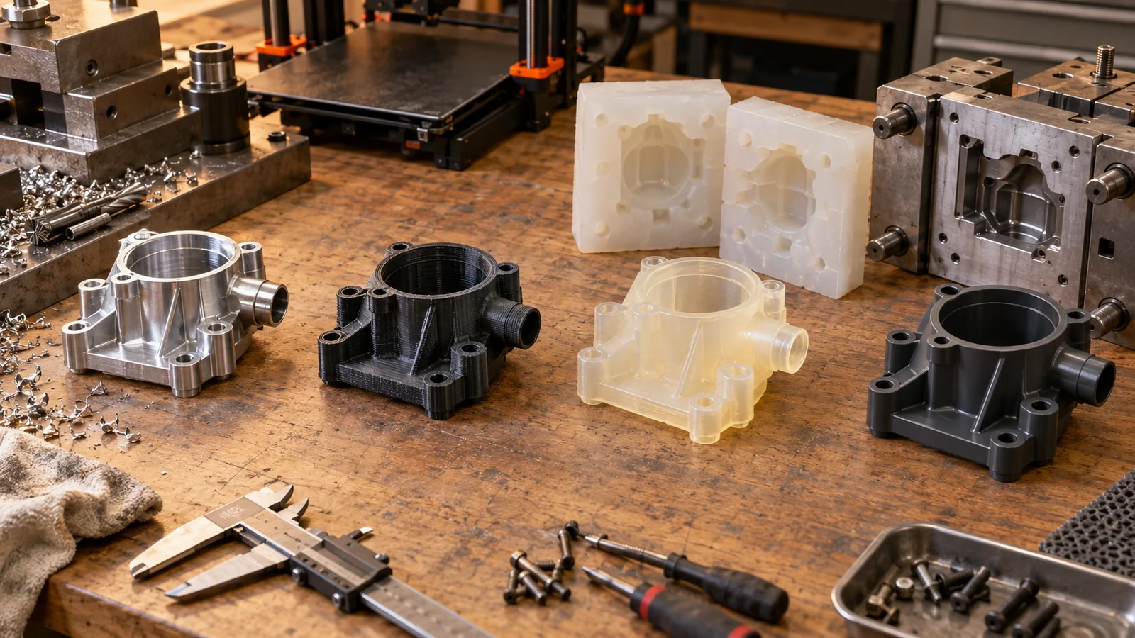
Process selection should answer two questions: what geometry can be made reliably, and what evidence does the current program stage require? CNC machining provides accurate interfaces and material-like behavior for many engineering plastics, but it cannot reproduce molded fiber orientation or every thin-wall feature. Additive manufacturing removes tooling and accelerates iteration, yet surface texture and anisotropy depend on the printing process.
Vacuum casting is useful when a small batch needs molded appearance and elastomer-like options. Injection molding becomes the reference when production material, repeatable cycle behavior, molded textures, living hinges, clips, or larger quantities matter. The following matrix keeps those differences visible.
| Route | Best evidence | Watch closely |
|---|---|---|
| mecanizado CNC | Fit, datum accuracy, machining-grade material behavior | Internal corners, residual stress, cost at quantity |
| impresión 3D | Fast geometry iteration and complex internal form | Build direction, surface finish, thermal limits |
| El vaciado al vacío | Small matched sets, color and tactile review | Material equivalence and mold life |
| El moldeo por inyección | Production-intent geometry, resin, texture and repetition | Tool investment, draft, gates, shrinkage and warpage |
When the design is approaching production, review it against the constraints of automotive injection molding even if early prototypes use another method. This prevents a visually successful prototype from carrying impossible undercuts, inconsistent walls, inaccessible shutoffs, or unsupported ribs into the tool-release stage.
Five Zones Cause Most Plastic-Part Rework
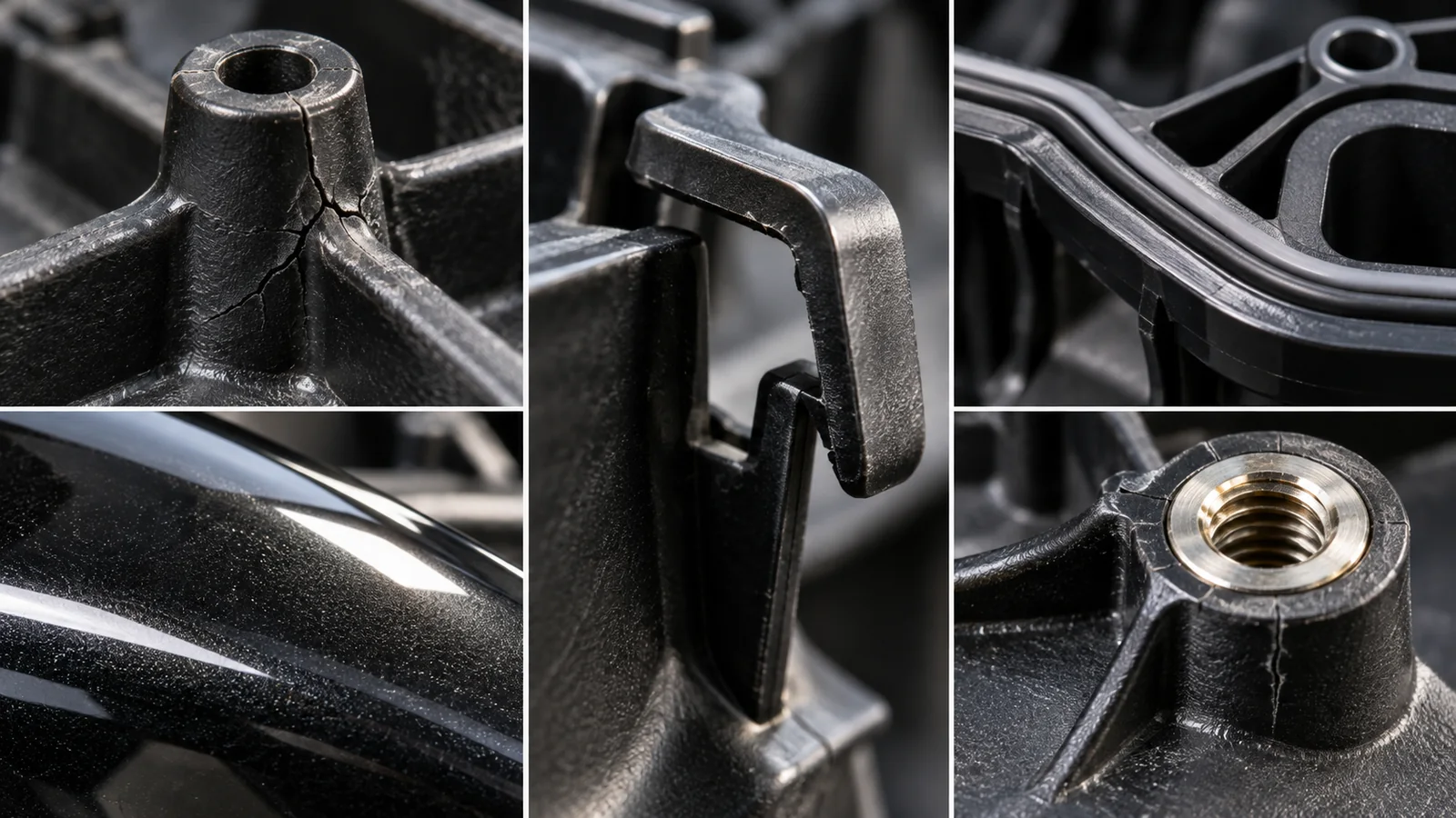
Bosses and fastener interfaces
Fasteners turn assembly torque into local hoop stress, compression, and long-term creep. Define the fastener, tightening method, washer or insert, service cycles, and load direction. A boss that survives one assembly can still relax after heat aging or crack when an operator uses the upper end of the torque range.
Snap fits and living features
A snap is a controlled deflection system. Root radius, arm length, engagement, strain, molding direction, and assembly access belong in the same calculation. Prototype the actual insertion path; hand-flexing an isolated feature rarely represents the surrounding housing.
Sealing flanges
Sealing depends on more than nominal dimensions. Flatness, joint stiffness, gasket compression, fastener spacing, surface texture, and thermal movement interact. The drawing should identify the functional sealing plane and avoid making every nearby surface equally critical.
Visible surfaces
Color, gloss, grain direction, weld lines, sink, gate witness, and parting lines should be reviewed together. A change that improves structural fill can move a weld line onto a visible face. Appearance approval therefore needs a boundary sample or measurable acceptance language, not only “match approved sample.”
Metal-to-plastic transitions
Threaded inserts, bushings, contacts, brackets, and overmolded conductors introduce different thermal expansion and stiffness. Provide retention against pull-out and rotation while keeping enough polymer around the insert to avoid splitting. The interface should be inspectable and should tolerate realistic assembly variation.
A Prototype Should Answer a Named Question
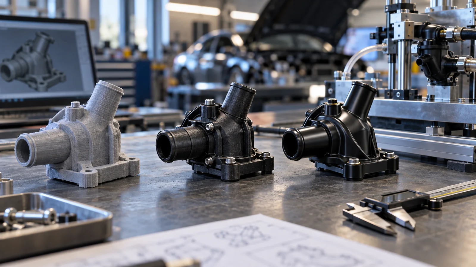
“Make ten prototypes” is not a test plan. Each build should have a decision attached to it: confirm package clearance, compare two latch geometries, validate heat-soak movement, assess texture, verify a gasket path, or train an assembly station. Once the question is named, the process, material, finishing level, and sample count become easier to justify.
For geometric learning, print or machine quickly and preserve iteration budget. For appearance learning, control color, texture, gloss, and assembly gap. For structural learning, choose a material and build orientation that do not create a misleading result. For process learning, move toward production-intent tooling and resin. Automotive rapid prototyping works best as a sequence of increasingly representative builds, not as a single “prototype” milestone.
Record the result in engineering language. Instead of “clip felt weak,” document insertion force, retention force, failure location, temperature condition, and cycle count. Instead of “panel fit looked good,” record the measured gap and flush condition at defined datum locations. This turns prototype observations into design input.
Production Release Needs a Control Plan, Not Just Approved CAD
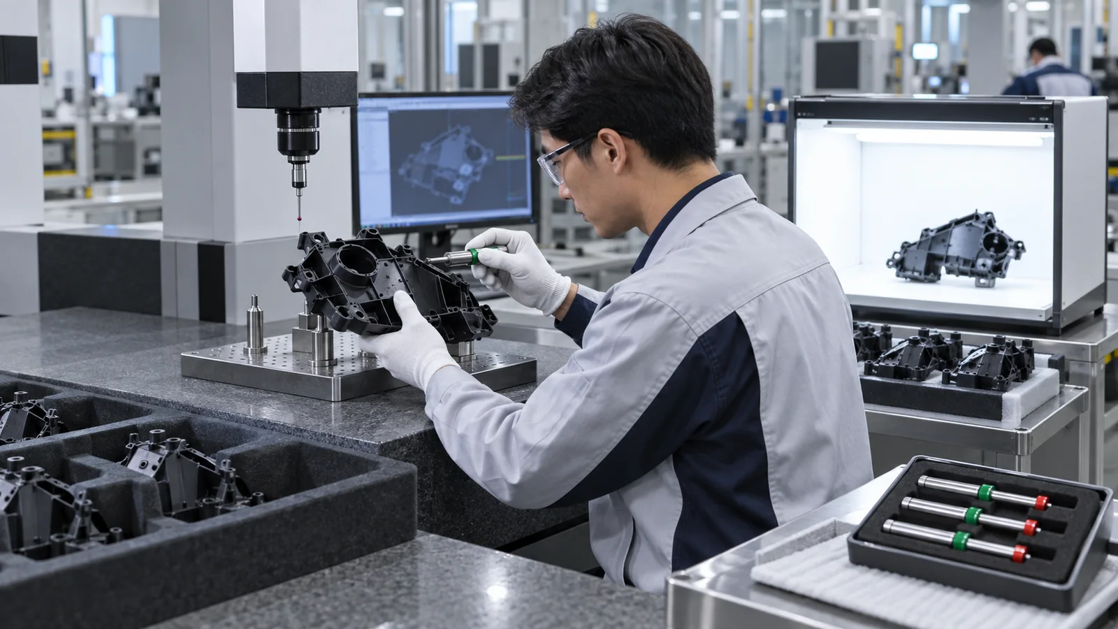
Before release, classify dimensions by function. Critical characteristics may include sealing flatness, connector location, optical alignment, clip engagement, or fastener position. General dimensions can follow a broader tolerance scheme. This distinction prevents inspection effort from being spread evenly across features that do not carry equal risk.
Agree how material condition will be controlled, especially for moisture-sensitive polymers and filled grades. Define cosmetic zones and acceptable limits for sink, flow marks, weld lines, gate vestige, flash, scratches, and color shift. Confirm packaging that prevents rub marks or deformation after inspection.
Finally, connect design changes to tooling and assembly consequences. Moving a rib may alter cooling and sink. Changing resin can affect shrinkage, weld strength, chemical resistance, and color. Tightening a tolerance may require a new datum strategy rather than more inspection. A cross-process supplier can coordinate prototyping, tooling, molding, machining, finishing, and subassembly so those effects are reviewed before they appear on the line.
Frequently Asked Questions
Which automotive plastic part should be prototyped first?
Prototype the component with the highest combination of interface uncertainty and change cost. Housings that control several connectors, seals, clips, or adjacent panels often deserve attention before simpler covers because one dimensional error propagates into multiple systems.
Can CNC-machined plastic replace an injection-molded validation part?
It can validate many dimensions, interfaces, and some material behavior, but it does not reproduce molding shrinkage, weld lines, molded-in stress, or fiber orientation. Use it for the questions it can answer and schedule production-intent molded parts for process-dependent validation.
How many internal links should this topic use?
Only links that help the reader make the next engineering decision belong in the article. The automotive industry page, the relevant process page, and the closest prototyping guide are normally more useful than a long list of loosely related services.
What information should accompany an RFQ?
Provide 3D data, controlled drawings, expected quantity, target material, finish and color, functional requirements, critical interfaces, validation stage, and known approval tests. Mark assumptions that are still open so the supplier can propose alternatives without silently changing the design intent.

