


3D printing car interior parts is most valuable when the build is treated as a cabin-development tool rather than a shortcut to a finished component. It lets teams evaluate reach, sight lines, switch access, vent direction, storage, gap and flush, tactile response, and assembly order before production tooling locks the design.
The challenge is deciding which interior questions a printed part can answer honestly. The right print may be rough and fast, cosmetically finished, mechanically representative, or built as a multi-part assembly. One print rarely does all four jobs well.
Cabin development route
Interior Prototypes Begin With People, Not Machines
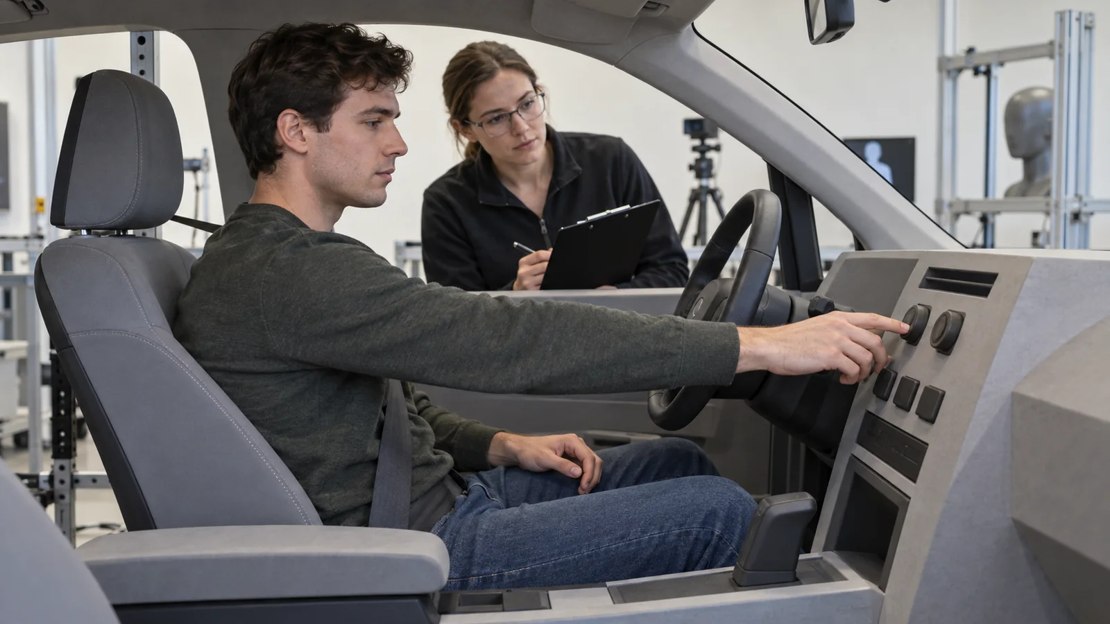
Cabin parts sit inside a dense human interface. A console may appear correct in CAD while a driver cannot reach a control without looking away from the road. A vent may fit the package yet send air into the steering wheel. A storage door may clear in isolation but contact a seat, cable, or occupant’s hand during use.
Define the evaluation scene before printing. Is the team checking a fifth-percentile driver, a gloved technician, a rear passenger, left- and right-hand-drive variants, or service access beneath the instrument panel? The physical mock-up should include the neighboring components needed to make that scene real.
Use the main automotive manufacturing page as the parent context, but keep this article’s scope narrow: it is about printed interior components and what they reveal about the cabin. Exterior aerodynamic models, metal powertrain parts, and generic printing explanations belong elsewhere.
A Better Part Split Produces a Better Test
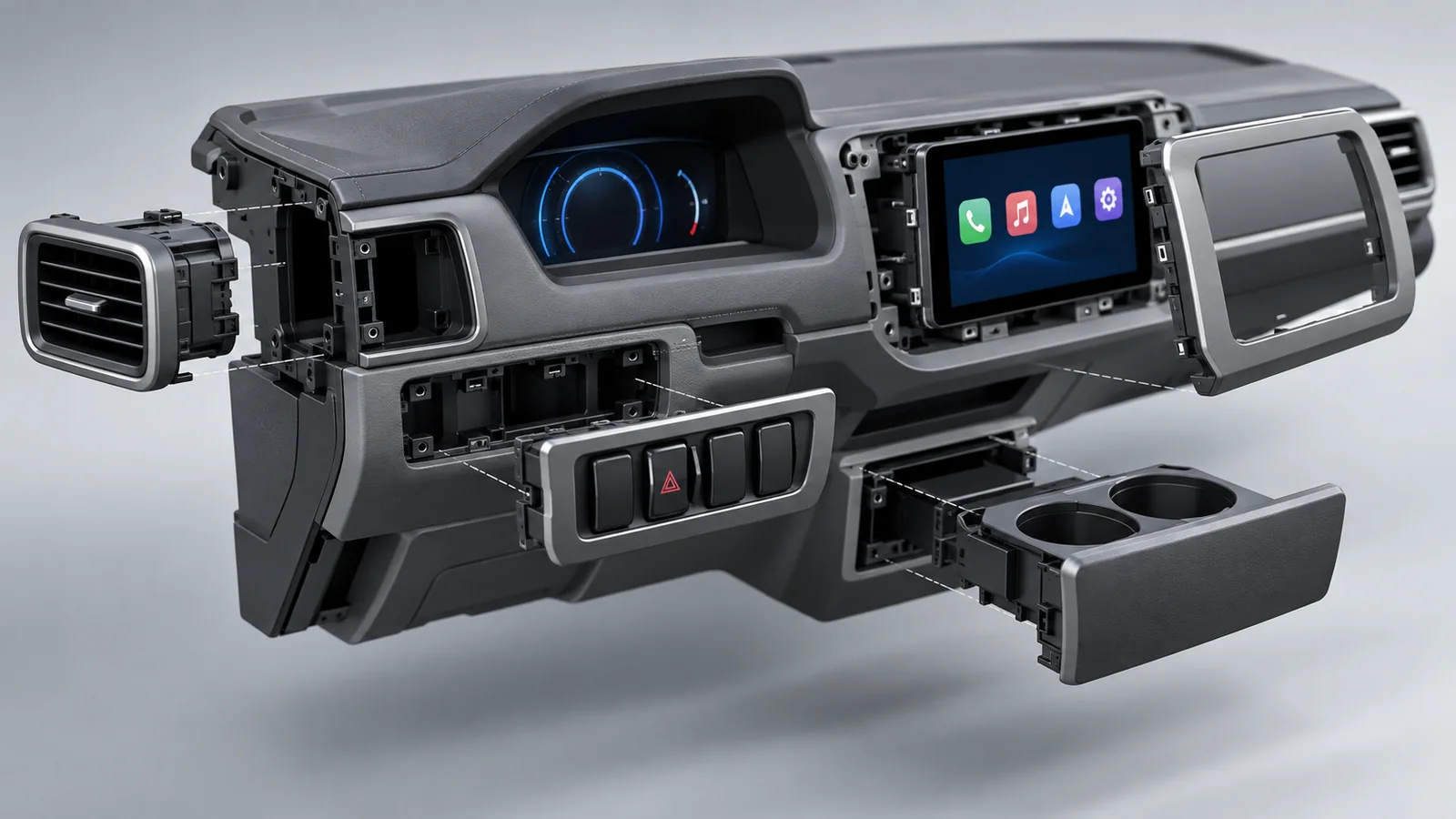
Large dashboard and door assemblies often exceed a printer’s build volume or become expensive monolithic jobs. Splitting the model is not merely a machine constraint. Deliberate split lines can make hidden fasteners accessible, allow alternate inserts to be swapped, isolate a high-wear feature, or let the team compare two surface treatments without rebuilding the whole assembly.
Place joints away from the visual or tactile question under review. Use dowels, tongues, dovetails, magnets, screws, or bonded backing plates according to the required repeatability. If gap and flush are being evaluated, the joint must not introduce more movement than the gap tolerance being discussed.
A modular buck is often more informative than a beautiful one-piece print. For example, a center-console body can remain fixed while teams swap cupholder geometries, switch bezels, charging pockets, and armrest hinges. Each variation becomes a controlled experiment rather than a new display model.
Select the Printing Process by the Evidence You Need
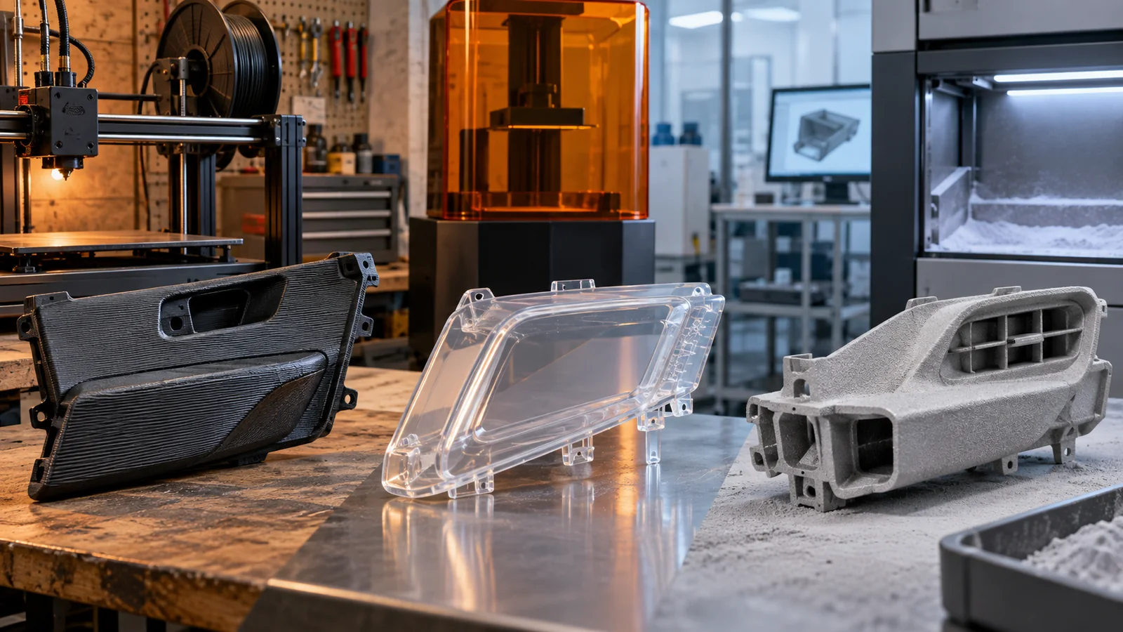
Fused filament fabrication is useful for quick package models, fixtures, and large low-cost forms. Stereolithography can produce fine detail and smooth surfaces for visual review. Selective laser sintering and related powder-bed processes suit robust clips, ducts, lattices, and assemblies without support scars. Material jetting can present color and tactile differences. Metal additive manufacturing has a narrower but valuable role for compact brackets, heat-resistant inserts, and highly integrated hardware.
| Review question | Useful route | Do not overclaim |
|---|---|---|
| Package and ergonomics | Fast large-format polymer printing | Production surface or long-term heat resistance |
| Fine visual detail | SLA or material jetting | Impact behavior of molded engineering resin |
| Clips, ducts and repeated handling | SLS/MJF engineering polymer | Molded fiber orientation and weld strength |
| Presentation model | Print plus controlled finishing | Unfinished dimensional evidence after heavy coating |
The existing guide to automotive 3D printing provides the wider process context. For cabin work, process choice should remain tied to touch, visibility, temperature, assembly cycles, and the exact decision due at the next design review.
Finish the Prototype Without Erasing the Truth
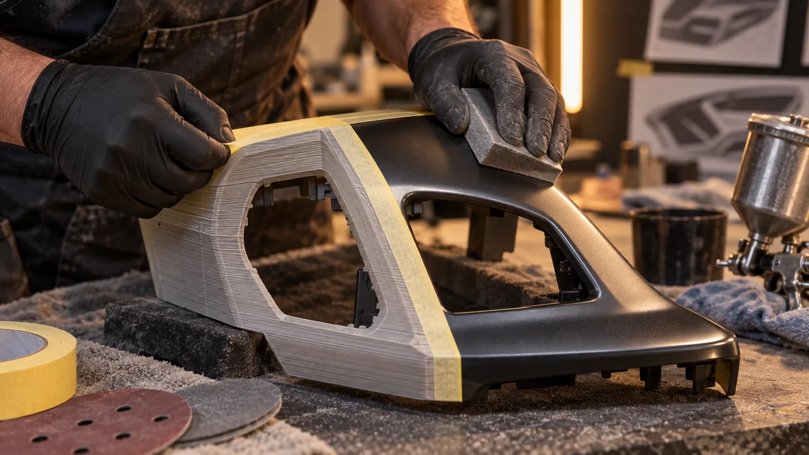
Sanding, filler, primer, paint, texture film, soft-touch coating, fabric wrapping, and printed graphics can transform a prototype. They can also alter edges, close small gaps, stiffen clips, and hide layer-related cracks. Separate appearance samples from engineering samples when the finish would contaminate the measurement.
For color and gloss review, define lighting, viewing angle, master sample, and zone. Automotive interiors combine low-gloss grains, high-gloss decorative areas, metallic accents, transparent lenses, and illuminated graphics. A single “black” callout does not control how adjacent parts will look under daylight and cabin lighting.
Texture scale matters. A grain that looks convincing on a flat coupon may stretch across draft and radii or collect finishing material in recesses. Use coupons to screen options, then apply the selected route to a representative curved section before finishing an entire instrument panel.
Turn the Cabin Buck Into a Test Instrument
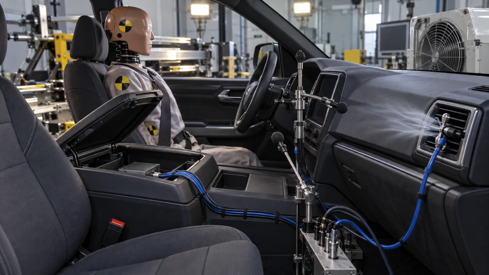
Begin with a fit map. Identify datum contacts, controlled gaps, flush relationships, moving envelopes, cable exits, and fastener access. Mark each observation directly against the digital model revision so the team does not approve a physical prototype that no longer matches current CAD.
Then run the human interactions: reach, grasp, push, pull, rotate, load, open, close, view, and service. Record the user condition and test sequence. A clip that survives casual handling may fail after repeated removal; a storage lid may feel acceptable empty but twist when loaded.
Thermal exposure is important even during early learning. A dark dashboard under solar load, a duct carrying conditioned air, and electronics behind a display create different temperature zones. Printed materials do not need to replicate production performance for every test, but the limitation must be stated so deformation is not mistaken for a geometry problem—or ignored when it reveals inadequate support.
Noise deserves its own review. Rattle and squeak paths occur at contacts, loose locators, cable movement, and differential expansion. Use the physical build to identify likely interfaces, then confirm them later with production-intent materials and fastening conditions.
The Production Handoff Starts Before the Final Print
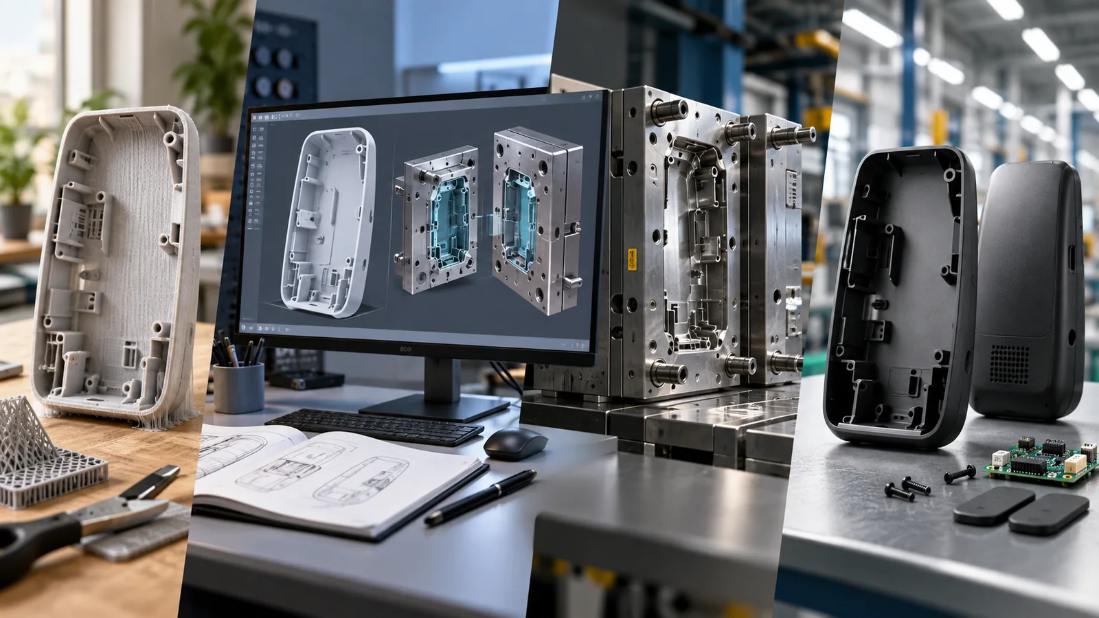
Every successful prototype should leave behind more than photos. Capture what changed, why it changed, which condition was tested, and what remains unproven. Update interface dimensions, tolerance assumptions, assembly sequence, and cosmetic zones while the observations are fresh.
Review the final geometry for molding, machining, trimming, joining, and finishing. Printed freedom can create trapped volumes, unsupported undercuts, inaccessible fasteners, or thin walls that do not translate into production. Connect the design to automotive injection molding requirements before tooling release, especially for clips, bosses, ribs, textures, and large visible panels.
Jucheng Precision can coordinate printed iterations with CNC-machined interfaces, molded development parts, sheet-metal brackets, finishing, and subassembly. The practical advantage is continuity: the questions discovered in the cabin buck remain visible when the program moves to a more production-representative process.
Frequently Asked Questions
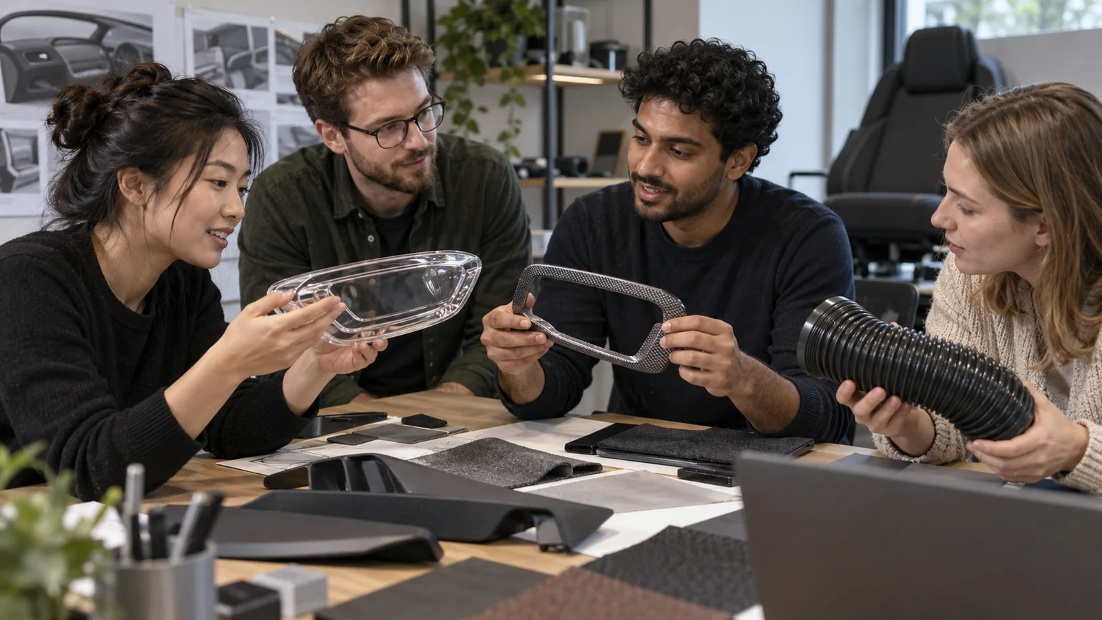
Can a printed interior part be used for vehicle testing?
Yes, when the test and limitation are matched. Printed parts can support package, ergonomics, airflow, assembly, and selected functional tests. They should not automatically be treated as evidence of production flammability, long-term UV stability, creep, odor, emissions, or molded impact performance.
Which cabin parts benefit most from 3D printing?
Instrument-panel sections, console modules, vents, ducts, switch bezels, display housings, cupholders, door-trim features, clips, brackets, cable guides, and service tools benefit because they involve dense interfaces or frequent design change.
Should the prototype use the final color and texture?
Only when appearance is one of the decisions. A geometry build can remain unfinished. A presentation or human-factors build may need controlled color, gloss, grain, and graphics. Keeping those purposes separate avoids unnecessary cost and misleading measurements.
How should a large dashboard prototype be divided?
Split it around the review plan: preserve important visible surfaces and gap relationships, create repeatable locating features, and make variable modules replaceable. Avoid joints through clips, seals, thin decorative edges, or the exact area being evaluated.

