


A timing cover can meet a free-state face measurement and still present a sealing problem after assembly. The mating structure, locating features, fasteners and seal arrangement all influence the installed condition. Automotive timing cover manufacturing therefore needs an interface review as well as a plan for making the cover itself.
The manufacturing question is specific: which features must remain related after casting, machining, finishing and assembly? Answering it early helps the buyer define a useful drawing, select a representative prototype and request inspection results that address the actual joint.
Begin at the joint, not at the outside shape
Review the sealing perimeter alongside its mating components. Depending on the design, a front cover may meet the engine structure, an adjacent cover or another joint surface. Where several joints meet, a small mismatch can matter even when each individual component has an acceptable appearance.
Identify the locating features separately from the fastening features. Dowels, pilots or defined faces may establish position while bolts provide retention. Manufacturing and inspection should reflect that division of function. Using clearance holes as convenient references can obscure the relationship the assembly actually needs.
Ask which sealing system the drawing specifies and where its requirements are controlled. Do not infer gasket compression, sealant thickness or surface texture from a similar cover. Those details depend on the approved design. The supplier needs enough information to manufacture the relevant surfaces without taking over responsibility for an unspecified sealing design.
An interface sketch can be more useful at this stage than a longer list of generic tolerances. Mark the sealing faces, locating points, seal bore and any controlled step between joints. Then connect each feature to a manufacturing operation and an inspection method.
Choose a prototype that answers the right question
Machining a cover from a suitable blank can provide an early geometry sample without waiting for production tooling. That sample can help check mounting access, surrounding clearance and selected interface dimensions. It does not reproduce every characteristic of a casting, especially where the manufacturing route changes local material or wall behavior.
A cast trial part answers different questions: whether the tool and process can produce the geometry, whether enough machining stock exists and whether defects appear when critical surfaces are opened. Treating these samples as equivalent can lead a team to approve a route using evidence from a different route.
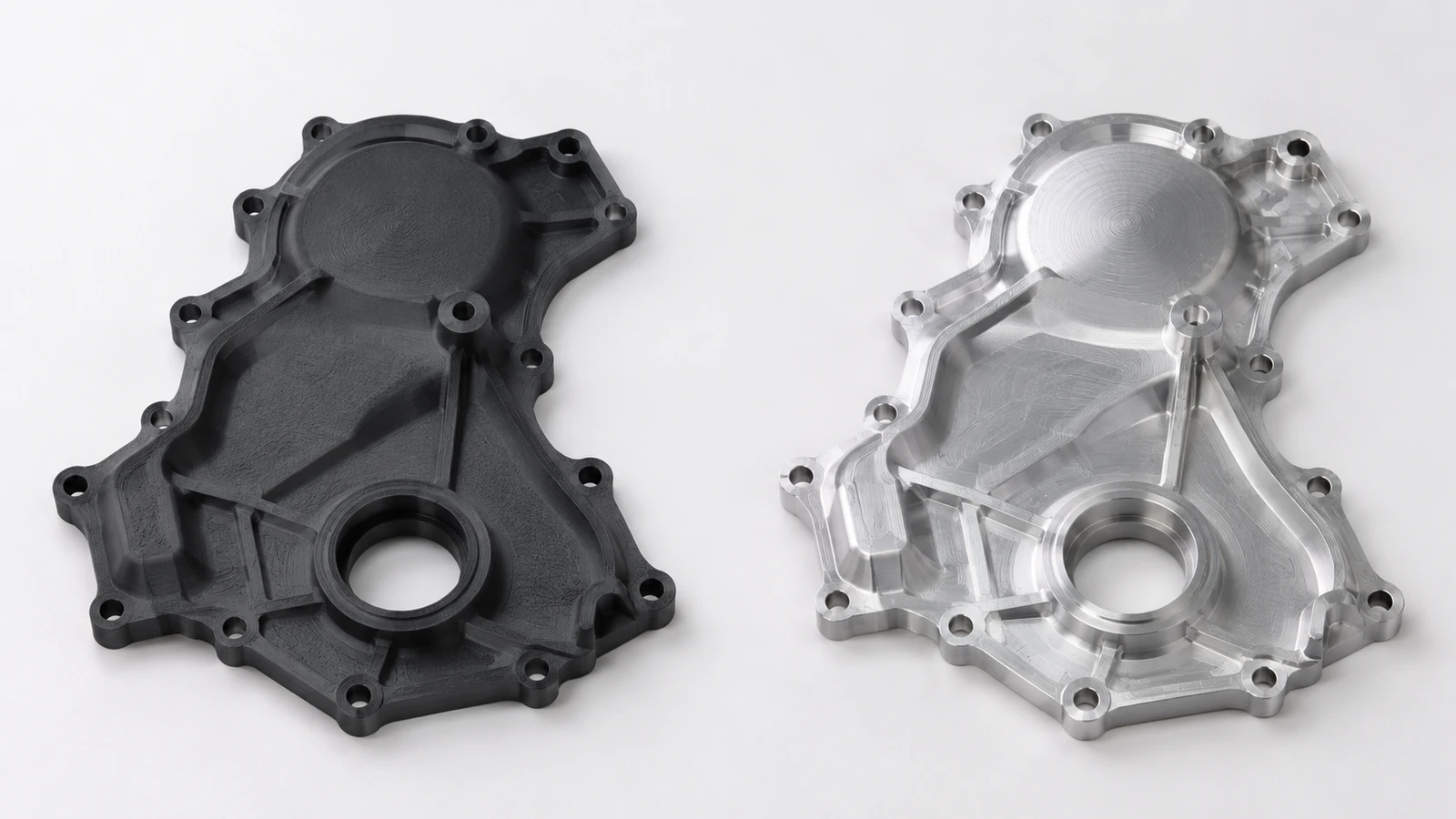
| Build purpose | Useful sample focus | Boundary to record |
|---|---|---|
| Packaging review | Envelope, attachment access and nearby components | May not represent final material or wall condition |
| Machining development | Datum access, stock allowance and fixture support | Needs a representative blank for route conclusions |
| Casting development | Fill, local quality and stock at machined interfaces | One trial does not establish sustained production capability |
| Assembly evaluation | The specified mating parts and fastening condition | Results apply to the evaluated configuration |
This choice belongs within the wider automotive manufacturing processes. State the purpose of the sample on the order so that a convenient prototype does not become an unintended production approval.
Casting and machining need a shared stock model
For an aluminum design, discuss the blank with both casting and machining requirements visible. The casting supplier needs a feasible geometry, while the machining supplier needs sufficient stock and reliable locating regions. A wall that looks adequate in the finished model may leave a difficult or inconsistent starting condition after casting variation is considered.
El die casting review should identify critical machined areas and the evidence needed for their local quality. Porosity that is not visible on an external skin may become relevant when a seal bore or face is machined. An attractive as-cast surface is not evidence about every internal region.
Specify how defects are evaluated and which repairs, if any, are permitted. Do not leave an assumption that a leak-related issue can always be resolved by an unapproved treatment. The customer-controlled requirements determine the acceptable route and any required verification after a corrective operation.
Before changing a rib, boss or section transition for casting convenience, review its effect on the functional interfaces. Manufacturing feedback is valuable, but a proposed change needs controlled approval. Record the accepted revision so that casting tools, machining fixtures and inspection programs refer to the same geometry.
Support the cover without forcing it into compliance
Thin or irregular covers can respond to clamping. A fixture should locate and support the blank in a way that gives the cutting operation stability without hiding the part’s behavior after release. A face that measures correctly while heavily restrained may not represent the required free or installed condition.
Map the cutting loads and support locations. Long unsupported spans, isolated bosses and interrupted cuts deserve attention because they can change how the part responds during machining. Avoid solving a support problem simply by applying more clamping force without evaluating the released result.
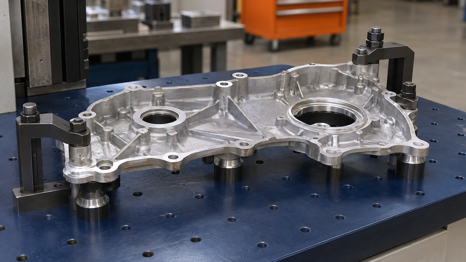
Where the design includes a shaft seal bore, preserve its specified relationship to the mounting references. Bore diameter alone does not establish location or orientation. A seal bore machined in a separate setup needs a defined datum transfer, with inspection capable of checking the resulting relationship.
For the aluminum machining plan, include burr control around intersecting holes and edges near the sealing perimeter. Deburring must remove unwanted material without rounding a controlled edge or damaging a sealing surface. Cleanliness requirements should be stated for the delivered part rather than assumed from a general visual check.
Diagnose a leak report in a useful sequence
First establish whether the reported issue concerns the cover, the joint system or the assembly condition. Record the exact revision, mating components, sealing materials and test configuration. Without that context, results from different builds may be compared as though they describe the same problem.
Next compare the relevant geometry in the required condition. Review the sealing surface, local steps and seal bore rather than immediately changing every machining tolerance. If the assembled condition is part of acceptance, use the defined setup and document it. An improvised fixture may create a different result without explaining the original issue.
Then examine the manufacturing history for changes at the affected interface. A different blank source, tool revision, fixture support or finishing operation may be relevant. Such changes are investigation leads, not automatic proof of cause. Use the evidence to decide which hypothesis deserves a controlled check.
Finally, keep dimensional and leak-test evidence separate but connected. A leak test needs its own specified conditions and acceptance criteria. Passing a dimensional report alone cannot replace it, while a passing leak result does not necessarily prove every drawing characteristic. Both records should identify the configuration actually evaluated.
What to include in the supplier handoff
Send the final part definition together with any available casting model, critical interface notes, inspection requirements and expected quantity. Identify whether supply includes casting, machining, finishing, purchased components or assembly. Make the scope explicit before comparing quotations.
Jucheng Precision can discuss a prototype route and review the machining access and material requirements for a defined timing-cover project. The review should focus on the seal interface, locating scheme and required evidence rather than on a generic promise of tight tolerances.
Agree on packaging that protects machined faces and prevents parts from rubbing against each other. Keep inspection records and approved deviations tied to the delivered revision. A successful handoff leaves the customer able to explain what was made, how the important interfaces were checked and which assembly questions still need confirmation.

