


Two sharp blades can still make a poor pair of scissors. The moving relationship between them, the pivot and the finished edge geometry determines how the assembly behaves. Surgical scissors manufacturing therefore requires attention to the matched instrument, not only to the dimensions of two separate blanks.
The focus here is conventional hand-operated instruments and their manufactured components. Robotic end effectors, powered systems and clinical technique involve different requirements. For an OEM project, the useful question is how to turn the controlled design into a repeatable assembly and an understandable acceptance record.
Observe the assembled motion before revising the blade
When a development sample does not meet its intended mechanical acceptance check, separate the observations. Does resistance occur through the whole stroke or at one position? Is there visible lateral play? Does the behavior change after the pivot is adjusted? These observations help organize the investigation without claiming to diagnose a device from appearance alone.
Record the exact sample configuration. Blade revision, pivot hardware, surface treatment and assembly adjustment can all affect the result. Comparing two samples without controlling these differences can lead to an unnecessary geometry change.
The design owner should define the appropriate mechanical test method and acceptance criteria. A workshop demonstration with an arbitrary material can be informative during development, but it should not become an undocumented substitute for the specified instrument evaluation.
Keep component and assembly findings connected. If a pair only behaves acceptably after extensive individual adjustment, the development team needs to know which feature or operation is driving that dependence. The answer may affect manufacturing sequence, inspection or assembly instructions rather than simply requiring a sharper edge.
Choose the blank and material condition together
A forged, cast or machined blank presents a different starting condition. The appropriate route depends on the controlled geometry, material, quantity and required evidence. The supplier should identify which features are produced in the blank and which are established during subsequent machining or grinding.
Material choice must account for the specified finished condition. A stainless-steel family name does not define hardness, heat treatment or every corrosion-related requirement. Request the actual material designation and processing specification rather than inferring them from a similar instrument.
For designs that specify a hardenable stainless grade, the 420 stainless steel machining discussion can help frame the relationship between rough machining and later finishing. It is an example of a material route, not a recommendation that every surgical scissor should use that grade.
Plan stock and references around required intermediate operations. If an operation can change geometry, the route needs a controlled way to achieve the final dimensions afterward. Leaving unspecified finishing stock creates uncertainty for both the machining supplier and the assembler.
Document substitutions and prototype exceptions. A soft material sample may be useful for checking handle clearance or general geometry, but it does not represent the behavior of a finished hardened instrument. Label its purpose so that it is not confused with a fully representative sample.
The pivot controls how the edges meet
Review the pivot hole or interface, its relationship to the blade and the allowed assembly condition. Local hole size alone may not establish the intended motion. The drawing should define the relevant geometry, while assembly instructions should define any controlled adjustment.

Inspect paired components in a way that preserves their reference. If each blade is checked independently, establish how the reported dimensions relate to the assembled condition. Otherwise, a collection of acceptable local measurements may leave the functional relationship unresolved.
Different designs use different blade forms and contact arrangements. Do not impose a universal gap, curvature or adjustment method. The supplier’s role is to understand and produce the specified geometry, then report where the proposed process or measurement method cannot establish it reliably.
This is where component machining connects to the broader medical device manufacturing processes. Milling, drilling, grinding, finishing and assembly should share a consistent part definition. A revision to one operation must be reviewed for its effect on the later steps.
Keep grinding and finishing from erasing the design
Edge creation and cosmetic finishing are not interchangeable operations. The route should identify which surfaces establish the cutting geometry and which receive a separate finish. A process intended to improve appearance can change an edge or transition if its limits are not controlled.
Discuss access and support for slender blades. A workholding arrangement that is adequate for a thicker section may not support a narrow tip in the same way. Evaluate the actual component and the required final geometry rather than relying on a generic fixture concept.
Deburring also needs a boundary. Remove unwanted material without rounding features that the drawing requires. Where the finished edge is intentionally sharp, handling and inspection should protect it while allowing the specified checks to be performed safely.
El acabado superficial specification should distinguish appearance from functional surface requirements. If a matte or reflective finish is requested, identify the affected regions and any areas excluded from treatment. Do not let a visual sample silently override dimensional or edge requirements.
After finishing, review whether earlier measurements still represent the delivered part. If a process removes material from a controlled surface, final acceptance may need to occur after that process. The sequence belongs in the manufacturing plan before production starts.
Use separate checks for separate failure modes
A useful acceptance package does not reduce the instrument to one pass/fail statement. It identifies the component characteristics, assembly behavior and delivered condition that were evaluated. The required methods and limits come from the controlled specification.
| Observation or requirement | Review focus | Evidence boundary |
|---|---|---|
| Uneven movement | Pivot, contact arrangement and assembly condition | One motion check does not identify every cause |
| Local blade mismatch | Profile and relationships between paired parts | External appearance may not establish the full geometry |
| Edge condition | Specified edge and transition features | Visual sharpness does not replace the defined test |
| Delivered surface | Finish, residues and handling damage | Clean appearance alone is not validated cleanliness |
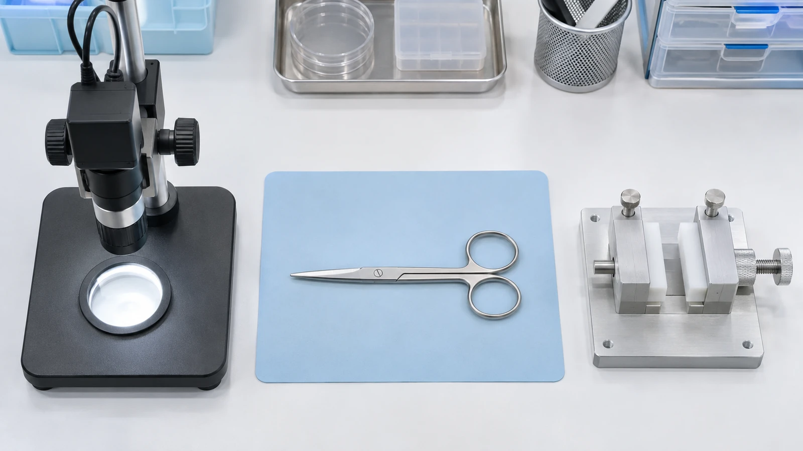
Record the instrument configuration used for assembly checks. If parts are matched, define how the pair remains identified through finishing and packaging. If interchangeability is required, that is a different manufacturing objective and should be stated explicitly.
A rejected sample should lead to a documented investigation rather than uncontrolled polishing or pivot adjustment. Identify the proposed correction, obtain the required authorization and repeat the relevant checks. This makes development learning usable for the next build.
Prepare an RFQ for the instrument you actually need
Provide component drawings and the assembly definition, not just a photograph of a similar scissor. Include material condition, finish zones, quantity, inspection requirements and whether the supplier delivers blanks, finished components or complete assemblies.
Identify which features require customer review before tooling or sample work begins. A clear issue list can include pivot interpretation, paired-part identity, final edge condition and the scope of any functional evaluation. It is more useful than an unqualified request for surgical precision.
Jucheng Precision can discuss prototype and component manufacturing around those inputs. The manufacturing review should establish access, sequence and inspection feasibility, while the device owner retains responsibility for the intended use and finished-device requirements.
Protect the accepted assembly during delivery. Packaging should prevent blade contact with unrelated parts and preserve any required pair identification. The customer should receive a clear record of what was manufactured, which checks were completed and which development questions remain open.

