


Interlocking cantilever closures require a precise balance of material elasticity, geometric strain distribution, and dynamic assembly clearances. Mastering the mechanics of designing snap fits for prototypes prevents fragile locking tabs from snapping during early functional validation checks. Many hardware developers encounter severe developmental bottlenecks because they test snap joints using rigid, brittle resins that fracture under minimal deflection strain. Introducing robust structural calculation methods early ensures lock clips actuate with a crisp, audible click without stressing mechanical joint roots.
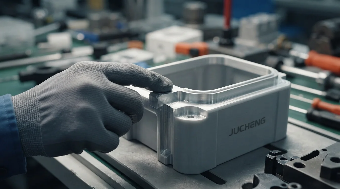
Sourcing physical validation models with optimized snap geometry helps engineering groups confirm assembly mating forces realistically. Mechanical specialists evaluate maximum strain-at-yield parameters, deflection limits, and parting lines using specialized CAD software. Resolving material brittleness and part clearance issues during early testing sweeps guarantees the physical enclosure functions exactly like mass-produced injection molded units. Technical design groups secure pristine surface finishes and robust mechanical strength by addressing process boundaries systematically.
Tabla de Contenidos
1. Biomechanical Physics of Cantilever Snap Joint Deflection
2. SLA Resin Limitations versus High Elasticity Materials
Biomechanical Physics of Cantilever Snap Joint Deflection
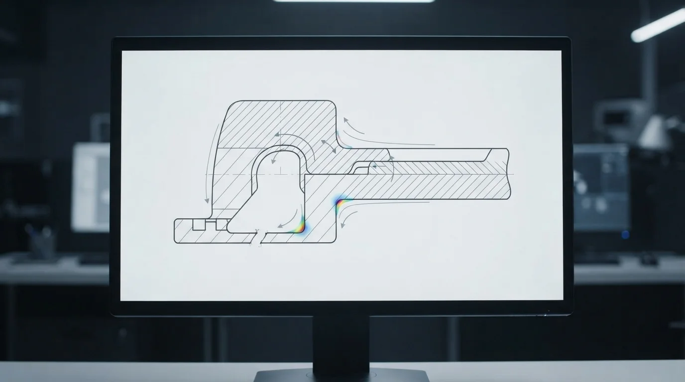
Question: What is the primary cause of snap fit breakage during prototype assembly? Exceeding the maximum allowable strain of the material at the root of the cantilever arm leads to immediate plastic deformation or structural fracture.
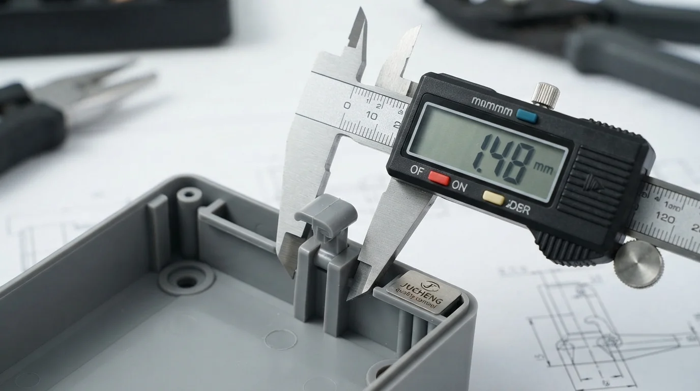
Cantilever snap-fit joints operate by temporarily deflecting an elastic arm over a mating retaining ridge before snapping back into a relaxed position. Stress concentrates heavily at the root of the cantilever beam where the arm meets the main enclosure wall. Designers must taper the arm thickness from the root to the tip to distribute bending stress evenly across the entire beam length. Failing to incorporate generous fillet radii at the inner root junction creates sharp corners that act as severe stress raisers.
Calculating maximum deflection strain before fabricating parts remains a mandatory step when designing snap fits for prototypes. Bending strain calculations dictate the maximum height of the retaining nose relative to the length and thickness of the cantilever arm. Selecting conservative deflection values prevents materials from exceeding their elastic limits, ensuring locking features remain reusable over multiple assembly cycles.
SLA Resin Limitations versus High Elasticity Materials
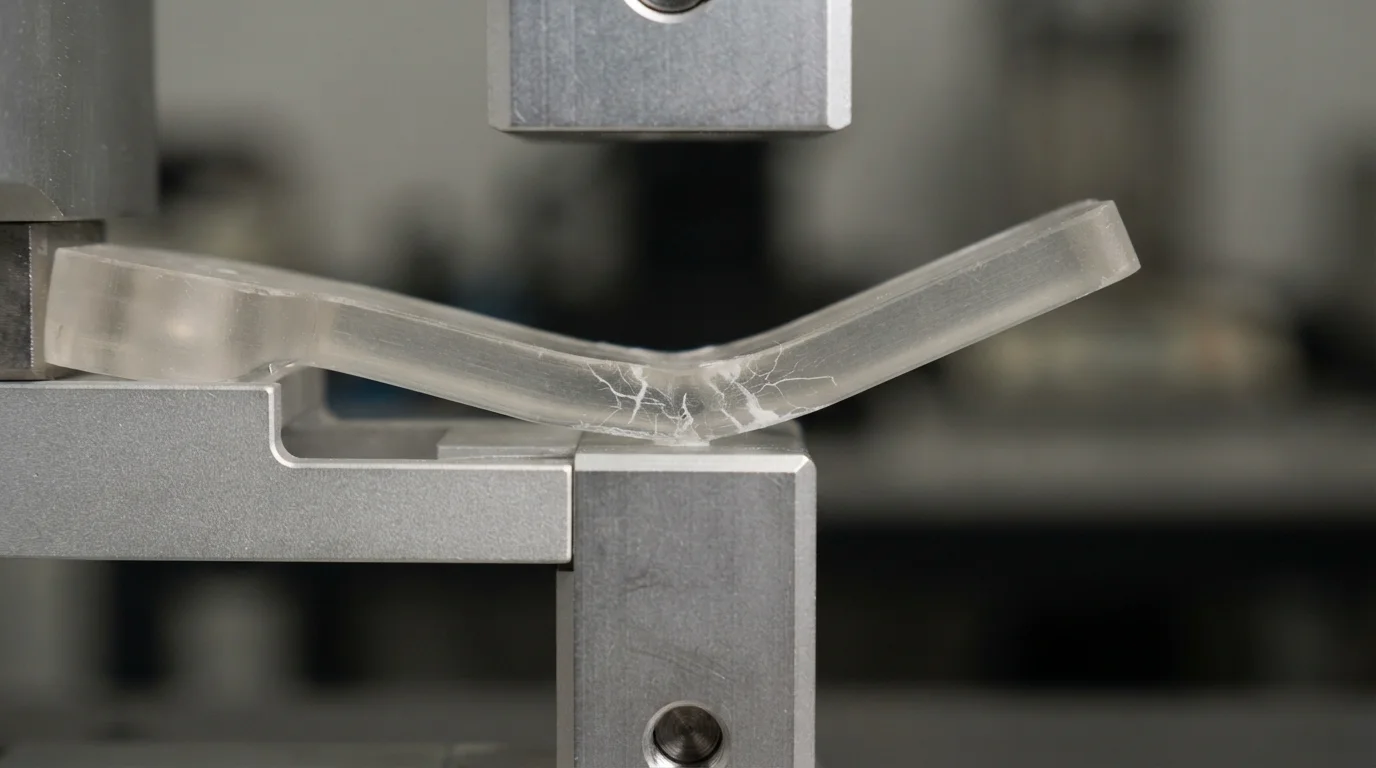
Question: Why do SLA photopolymer prototypes make poor snap fits? Standard photopolymer acrylic-like resins are highly brittle and lack the elastic elongation properties required to survive bending strains.
Las resinas estándar de fotopolímero para estereolitografía imitan la claridad visual y la forma rígida de los termoplásticos de producción, pero poseen límites de elongación a la rotura muy bajos. Doblar una lengüeta en voladizo impresa en SLA más allá de su umbral elástico mínimo induce microgrietas instantáneas en la raíz con concentración de tensiones. Implementar principios de diseño de prototipado rápido principios garantiza que los equipos mecánicos eviten resinas frágiles para pruebas cinemáticas funcionales. Especificar polvos SLS resistentes y de alta elongación o plásticos mecanizados preserva la integridad de las piezas durante ensayos dinámicos de validación de ajuste físico.
Seleccionar el material estructural correcto implica equilibrar los parámetros de elongación en el límite elástico con los costos generales de fabricación. Los plásticos de ingeniería de alto rendimiento como Delrin (POM), Nylon 66 y ABS de alto impacto representan el estándar de la industria para evaluaciones funcionales de ajuste a presión. Esta tabla comparativa técnica destaca las propiedades básicas del material críticas para el rendimiento de las uniones a presión:
| Designación del Material | Módulo de flexión | Elongación en el Límite Elástico | Idoneidad Principal para Ajuste a Presión |
|---|---|---|---|
| Delrin (POM) | 2.8 GPa | 10% a 15% | Recuperación elástica excepcional, excelente resistencia al desgaste |
| Nylon 66 (Sin Relleno) | 2.5 GPa | 8% a 12% | Alta resistencia a la fatiga, excelente flexibilidad dinámica |
| ABS (Impacto Medio) | 2.1 GPa | 5% to 8% | Balanced stiffness and impact toughness |
| SLA Durable Resin | 1.8 GPa | 8% to 10% | Moderate flexibility, lower fatigue limits |
FDM nylon filaments also provide functional alternatives, but inter-layer bonding weaknesses can lead to delamination along shear plane directions under dynamic stress. Machined or rapid-molded engineering plastics provide isotropic grain layouts, ensuring consistent mechanical behavior across all coordinate axes. Engineers confirm structural repeatability by conducting rigorous cyclic clip-and-release testing.
Subtractive CNC Milling and Rapid Tooling Validation
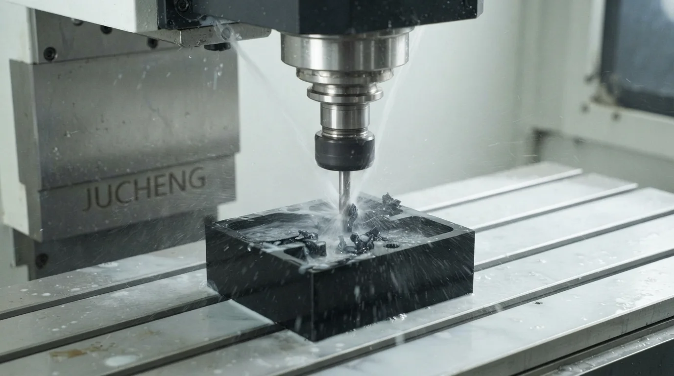
Question: What is the most reliable way to machine functional snap joints for testing? Micro-CNC milling from extruded Delrin or Nylon bars delivers pristine features with isotropic mechanical behavior.
Subtractive CNC milling from solid engineering plastics ensures locking clips undergo realistic flexing without experiencing layer delamination defects. Jucheng Precision operates a fully equipped manufacturing workspace containing 150+ CNC machines, including 25 high-precision Haas/Mazak de 5 ejes milling centers. Advanced multi-axis milling cuts micro-undercuts and sharp catch angles with sub-micron coordinate repeatabilities. Machined POM or Nylon clips actuate with precise mating forces, allowing engineers to calibrate snap retention limits accurately.
Successfully executing the step of designing snap fits for prototypes in pre-production phases involves proving out mold ejection behaviors. Factory teams deliver comprehensive DFM gratuito las 24 horas reviews to optimize mating clearances, wall uniformity, and parting line split lines before cutting tool steel. Specialized utillaje rápido molds deliver genuine injection-molded components within 4 to 15 days, helping design groups bypass long developmental lead times. Operating under a strict no-MOQ policy enables mechatronics groups to refine customized lock mechanisms safely.
Preguntas Frecuentes (FAQ)
What is the maximum strain limit for a cantilever snap fit using ABS?
Designers must restrict peak deflection strain to 5 percent when designing snap fits from ABS polymers to prevent permanent plastic deformation. Sizing cantilever arms with generous lengths relative to thickness keeps strain levels safely within this elastic limit.
Why are sharp internal corners problematic for cantilever snap fits?
Sharp internal corners concentrate mechanical bending stress, causing micro-cracking and eventual part failure at the root of the dynamic cantilever arm. Incorporating fillet radii of at least 50% of the nominal wall distributes stress evenly.
Can rapid tooling molds handle complex snap fit undercuts?
Aluminum rapid tooling molds handle complex snap-fit undercuts efficiently using mechanical sliding lifters or spring-activated slide cores. Sourcing early DFM reviews simplifies split line layouts, eliminating the need for expensive mold actions.

