


A laser mark that looks sharp on the day of production may still be unsuitable for a medical device. Cleaning can reduce contrast, sterilization can change the substrate, abrasion can remove shallow marks, and a curved surface can distort a machine-readable code. Medical device laser marking must be designed around the complete service life of the identifier, not around the first successful sample.
The engineering task connects regulatory data, material behavior, optical contrast, geometry, process control, and verification. This guide shows how to translate identification needs into a marking specification that a manufacturer can develop, inspect, and reproduce.
Contents
Define the Job Before Choosing the Laser
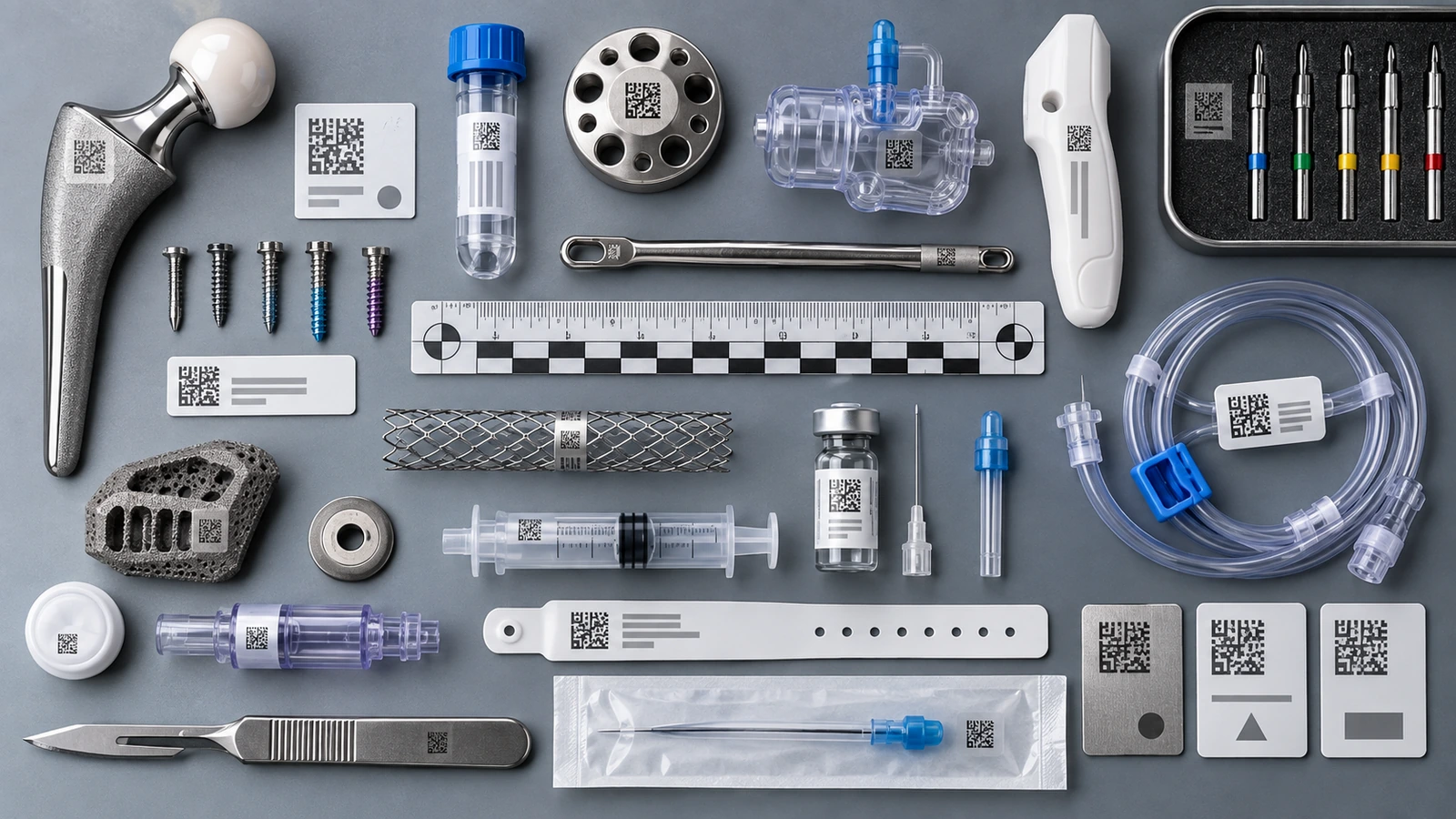
The word mark can refer to a logo, serial number, lot code, scale, instruction symbol, alignment feature, or Unique Device Identifier. Those functions do not share the same acceptance criteria. A human-readable label needs adequate character form and contrast. A machine-readable code also needs cell geometry, quiet zone, symbol quality, and scanner access. A process mark used only during assembly may need different durability than permanent device identification.
| Requisito | Design question | Evidence |
|---|---|---|
| Human readability | Viewing distance, lighting, font, contrast, curvature? | Defined visual inspection and reference standard |
| Machine readability | Scanner type, code size, quiet zone, orientation? | Code grading or verified read test |
| Durabilidad | Cleaning, sterilization, abrasion, chemicals, UV? | Post-exposure readability and surface review |
| Traceability | Which database field, serial logic, and record links apply? | Data reconciliation and device-history record |
The U.S. Food and Drug Administration’s UDI overview explains the role of device identifiers and production identifiers in the U.S. system. The marking engineer should receive the approved data structure rather than inventing content at the machine.
The Substrate Creates the Mark
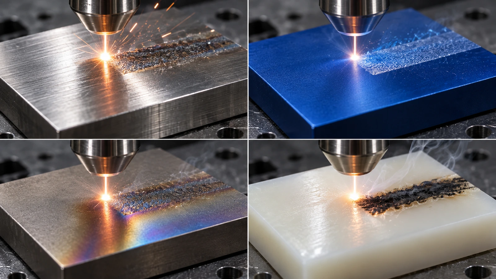
A laser does not apply a universal black image. It changes the material through ablation, annealing, foaming, carbonization, color change, engraving, or another mechanism. Wavelength, pulse behavior, energy density, focus, speed, shielding, and surface condition interact with alloy, polymer grade, pigment, coating, texture, and heat treatment.
Stainless steel may support an annealed contrast mark with limited material removal when the surface and parameters are suitable. Aluminum response depends strongly on anodizing, coating, and alloy condition. Titanium can discolor through oxide formation but excessive heat input may affect the surface. Polymers vary widely: a base resin and its colored or laser-markable grade can produce entirely different contrast and damage behavior.
Material selection should therefore stay connected to the parent topic of medical device materials. If the exact supplier grade, colorant, finish, or coating changes, the approved laser recipe may no longer produce equivalent results.
Sample development should use
- The production-intent alloy or polymer grade
- The intended surface finish, coating, texture, and color
- Representative wall thickness and heat-sink condition
- The real mark size, geometry, and location
- The expected cleaning and handling state before marking
Give the Code Enough Physical Space
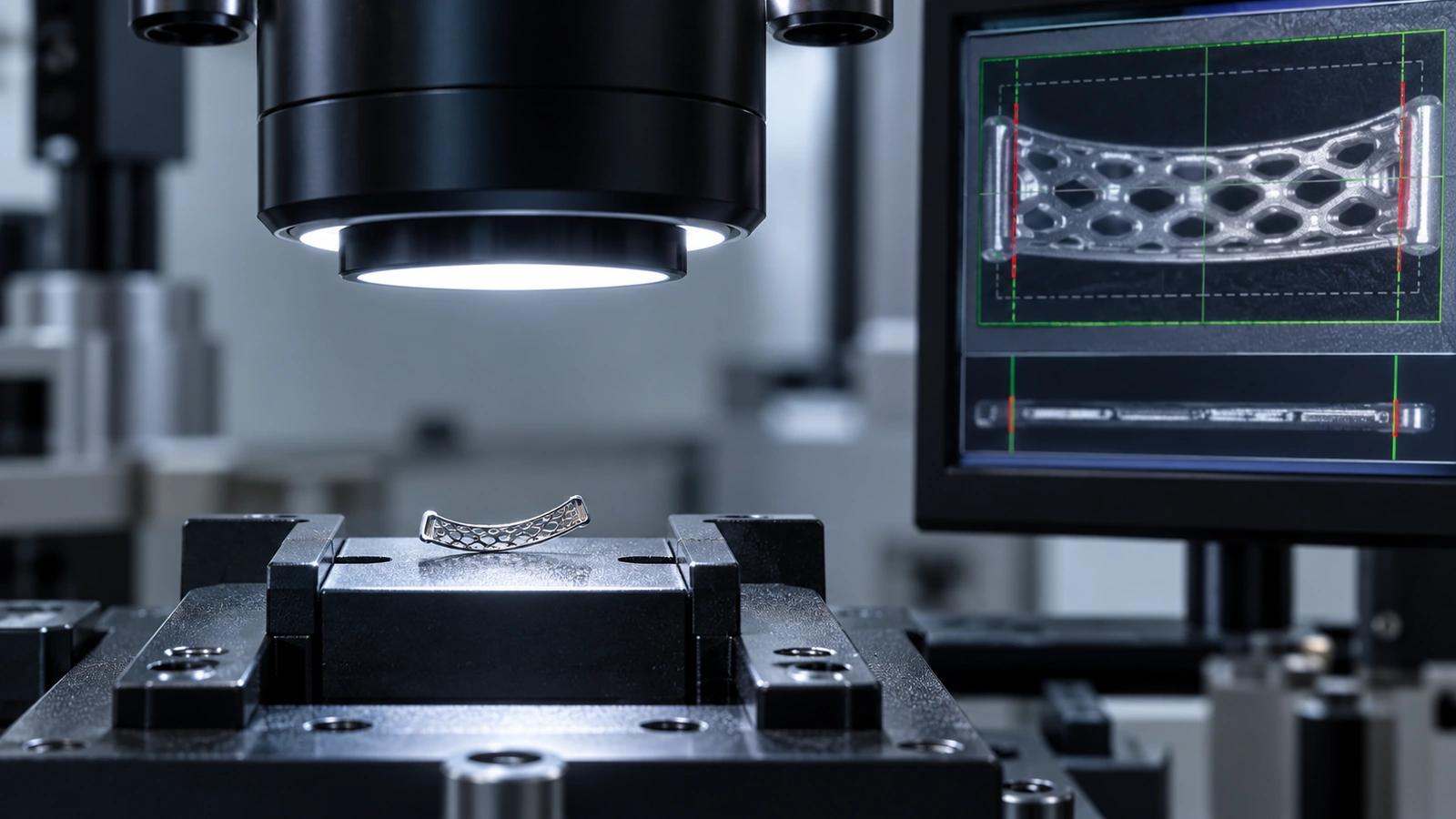
Design teams often reserve a marking box late, after ribs, fasteners, curvature, texture, and cosmetic zones are fixed. The result may force a small code onto a curved or reflective surface where the scanner cannot view it consistently.
Create a controlled marking zone early. Consider code dimensions, quiet zone, edge distance, focal-depth variation, fixture access, part orientation, and whether the surface can be held repeatably without damage. Avoid placing a code across a weld, severe texture transition, thin unsupported wall, or surface that receives later machining or coating.
A marking zone is a functional interface between the device, the manufacturing cell, the reader, and the traceability database.
For assembled devices, confirm whether the identifier remains visible and scannable after covers, cables, and accessories are installed. If a mark is used during assembly, define its orientation relative to the fixture and operator workflow.
Develop a Process Window, Not a Favorite Setting
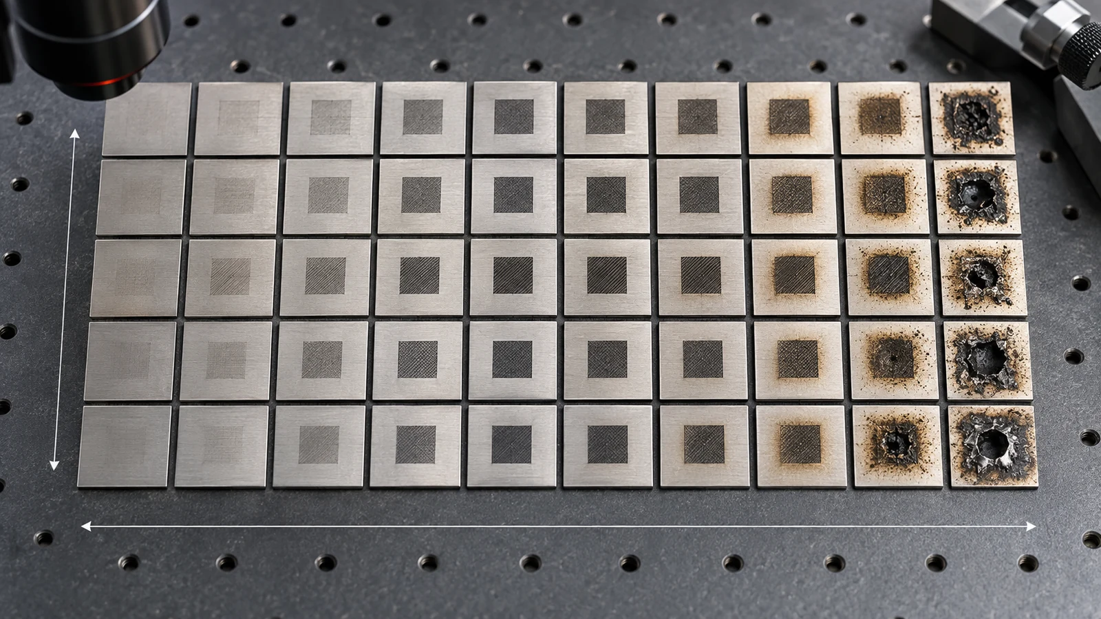
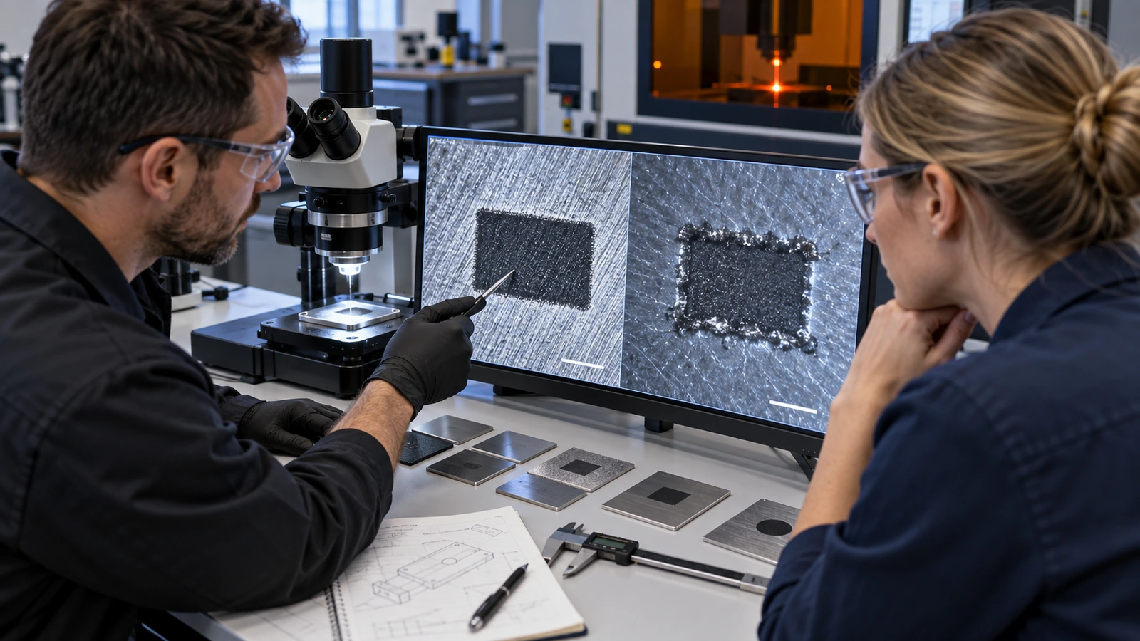
A single parameter combination may produce an attractive sample but offer little tolerance to material or focus variation. Development should explore the inputs that control contrast, depth, edge quality, heat effect, residue, and code readability.
- Screen: identify promising wavelength, focus, speed, power, frequency, pulse, and pass combinations.
- Desafío: test realistic material lots, surface conditions, fixture positions, and allowable focus variation.
- Measure: use defined visual, dimensional, surface, and readability outputs.
- Select: choose a robust region rather than the single darkest sample.
- Lock: control recipe, software, artwork, fixture, and approved material state.
The development plan belongs within the broader medical device manufacturing processes framework. Marking may occur before or after passivation, anodizing, coating, cleaning, or assembly, and sequence can change both appearance and durability.
Verify the Mark After Realistic Exposure
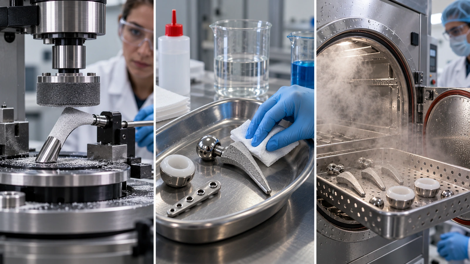
Initial contrast is only the baseline. Build an exposure matrix from the device’s intended life: cleaners, disinfectants, sterilization, abrasion, handling, UV, humidity, temperature cycling, and any contact with fixtures or packaging. Evaluate both readability and substrate damage after exposure.
Machine-readable marks should be tested with the intended reader population and realistic angles, lighting, and surface condition. A code that reads with a laboratory scanner directly above the part may fail on the assembly line or in service. Human-readable content needs a controlled visual standard so acceptance does not depend on one inspector’s preference.
Failure modes worth looking for
- Reduced contrast or color shift
- Cell growth, melting, or edge rounding
- Glare from reflective surfaces
- Corrosion or altered passivation behavior
- Cracking, burning, raised debris, or trapped residue
- Code distortion from curvature or fixture error
- Mismatch between marked data and electronic record
Control the Data as Carefully as the Beam

A technically perfect mark with the wrong serial number is a traceability failure. The marking system should control approved artwork, data format, serial generation, duplicate prevention, user permissions, software revision, rejected code handling, rework, and reconciliation between marked parts and production records.
Define what happens after an interrupted cycle. Can the machine repeat the same serial? How is a scrapped marked component recorded? Who can edit static text or code layout? How does the system prevent a template for one model from being loaded on another? These controls belong in work instructions and software or data validation, not in tribal knowledge.
Integrating Marking With Part Manufacture

Jucheng Precision can coordinate laser marking with CNC machining, sheet-metal fabrication, molding, casting, surface finishing, inspection, and assembly. Integration helps the team choose the correct sequence and evaluate the mark on production-intent material and finish.
For a machined instrument component, marking may need to follow cleaning and passivation. For an anodized aluminum enclosure, the mark depends on coating specification and cosmetic acceptance. For a molded polymer housing, resin grade, pigment, texture, and gate-related appearance can influence contrast. Jucheng’s surface finishing services provide the surrounding process context needed to plan that sequence.
Laser Marking FAQ
Is laser marking permanent?
Permanence depends on the marking mechanism, substrate, depth or color change, surface condition, service exposure, and acceptance requirement. A mark should be qualified against the intended device life rather than assumed permanent because it was made by laser.
Can one laser recipe be used for every grade of a polymer?
No. Pigments, fillers, additives, texture, moisture, and supplier formulation can change absorption, contrast, damage, and residue. Approve the exact material state or define and test a justified family.
Should a laser mark be applied before or after surface finishing?
The correct sequence depends on the finish and desired mechanism. Later coating may cover a mark, while marking after passivation or anodizing may affect appearance or surface performance. Develop and verify the complete sequence.
How is a Data Matrix code inspected?
Use a defined verification or read method appropriate to the code and application. Control lighting, angle, optics, code size, surface curvature, and software settings. A simple successful scan is useful but may not characterize symbol quality.
Does laser marking replace labels?
Not automatically. The required information, device design, market, packaging, and use environment determine whether direct marking, labeling, or both are appropriate.
Specify the Identifier as a Device Feature
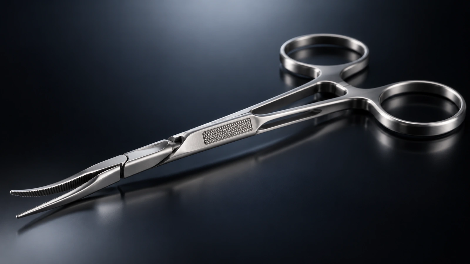
Medical device laser marking performs reliably when the identifier is treated as a functional feature with defined data, geometry, material state, process window, exposure, and verification. Reserving the area early prevents a late identification requirement from becoming a device redesign.
Send Jucheng your part files and marking requirements to review material response, process sequence, code location, and production controls.

