


A payload adapter plate is a geometric contract between a spacecraft bus and the payload it carries. Its bolt pattern, interface plane, stiffness, mass properties, clearances, and access features must agree with two sides of an integration stack that may have been designed by different teams. A plate can be beautifully machined and still be unusable if one interface is referenced from the wrong datum or a fastener tool cannot reach the assembled joint.
So what should be checked before a satellite payload adapter plate enters manufacturing? Start with the interface-control data and the assembly sequence, then develop a manufacturing and inspection plan that preserves those relationships. The article connects this work to aerospace component prototyping and manufacturing, while leaving mission qualification and launch approval to the responsible program authorities.
Contents
- Read the interface-control definition before the model
- Translate loads and stiffness into inspectable geometry
- Design access into holes, pockets, and cable paths
- Compare material options against the mission need
- Protect the two interface planes during machining
- Verify the plate in its actual measurement frame
- Use a staged build to reduce integration surprises
- Integration questions worth answering early
Read the interface-control definition before the model
The adapter’s first manufacturing input should be the controlled interface definition: mating diameters or envelopes, bolt-circle data, fastener type, orientation references, keep-out zones, and any alignment or clocking requirements. Check that the bus-side and payload-side coordinate systems are clearly related. A 180-degree rotation or a mirrored hole pattern can be hard to notice in an attractive CAD rendering yet become obvious only during integration.
Compare the model, drawing, and interface-control document. Confirm which is authoritative for dimensions and revision status. Check whether the adapter has a primary plane, a centerline or axis, and a clocking feature that unambiguously sets orientation. If the two mating assemblies use different coordinate frames, document the transformation rather than expecting the supplier to infer it.

Also identify the actual assembly direction. If the plate is installed from one side, fastener heads, tool clearance, and access to captive hardware may constrain pocket and counterbore geometry. If access is limited after payload placement, assembly sequence may require pre-installed hardware, service clearances, or handling features. These details should be settled before machining because they can change the part layout.
Translate loads and stiffness into inspectable geometry
Payload adapters often carry demanding launch and operational loads, but a manufacturing article cannot determine the correct load cases. Those come from program analysis and the approved design basis. The manufacturing review should instead ask how the released design expresses those needs: which faces carry load, which regions are structurally sensitive, and what geometric characteristics must be controlled so the finished part matches the analyzed configuration.
Large pockets, cutouts, and weight-reduction features can reduce mass but also reduce local stiffness and alter how the plate behaves under clamping. If the design includes thin webs between bolt lands, verify that tool access and inspection remain possible. Avoid changing pocket depth, rib thickness, or edge distance as a shop convenience unless the change has the required engineering approval.
Make requirements measurable. If a flatness, parallelism, position, or surface condition is important, define its datum reference and acceptance method. A broad statement such as “precision interface” is not enough for quoting or acceptance. The drawing should identify which plane establishes the assembly reference, how the opposing interface relates to it, and which features are functionally located.
Design access into holes, pockets, and cable paths
Review every bolt hole for drill or cutter access, edge distance, countersink or counterbore geometry, and deburring. Check whether the mating fastener requires a wrench, socket, or other tool envelope. A hole can satisfy a nominal coordinate and still be difficult to assemble if a nearby rib, payload wall, or harness blocks the tool.
Where the plate contains cable slots or connector openings, trace the full connector and bend envelope rather than just the cutout. Consider installation and service access, strain relief, and whether a cable path crosses a structural land. The supplier should machine the released geometry, but design teams can avoid late revisions by including the real mating hardware and cable routing in the review.
Deep pockets and intersecting cavities need a plan for chip evacuation and inspection. Sharp internal corners may be limited by cutter radius; an inaccessible corner may trap debris or require a different design detail. Chamfers can support assembly, but excessive edge breaks may reduce bearing area around fasteners. Decide which edges are functional, which need deburring only, and how the condition will be verified.
Compare material options against the mission need
Material should be selected by the approved structural, thermal, environmental, and mass requirements, not by machinability alone. Aluminum alloys may be considered where a favorable mass-to-stiffness balance and machined plate construction fit the application. Titanium alloys or other specified materials may enter the discussion when the program’s design basis calls for different strength, temperature, or interface behavior. These are trade-space examples, not blanket recommendations.
| Review topic | Question for the design team | Manufacturing implication |
|---|---|---|
| Alloy and temper | Which exact specification and condition are approved? | Controls procurement records and machining assumptions |
| Part thickness | Which regions must retain stiffness or interface height? | Influences stock size, clamping, and distortion risk |
| Surface treatment | Which areas need protection or specific contact behavior? | May change dimensions and require masking or post-finish checks |
| Mass properties | What calculation and configuration govern acceptance? | Requires controlled geometry and approved evaluation method |
Document material substitutions explicitly. A fit-check plate made from a different stock can validate assembly access, but it does not demonstrate stiffness, strength, thermal behavior, or launch performance of the intended hardware. The aerospace materials reference can frame early questions; the current released drawing and procurement specification control the build.
Protect the two interface planes during machining
Plan the sequence around the bus-side and payload-side references. Establish a stable datum, rough pockets while retaining support where useful, and finish the critical planes and patterns using a defined relationship. If the part is flipped, the route must explain how the first reference is transferred and verified. A setup sketch or operation plan can help the engineering and quality teams review that logic before chips are made.
Clamping is especially important for a broad plate with pockets or thin sections. Excess force can distort a region that springs back after release; too little support can allow vibration or movement. Use a fixture strategy consistent with the geometry, and evaluate critical planes in the state specified by the drawing. The goal is not a particular machine count but a repeatable route that holds the intended interface relationships.
Surface treatment and marking may follow machining. Define masking, contact areas, identification location, and any characteristics that must be checked after treatment. Protecting bolt seats and reference surfaces can matter as much as the nominal surface finish elsewhere. If an identification mark is required, ensure it does not occupy a load-bearing or mating surface without approval.
Verify the plate in its actual measurement frame
Inspection should use a coordinate frame that mirrors assembly intent. Check the primary plane, opposing plane, hole pattern, center references, and clocking feature from the specified datums. Where applicable, inspect the assembly pattern as a pattern rather than as unrelated hole coordinates. A report that lists individual diameters may not answer whether the payload can be clocked and fastened as designed.
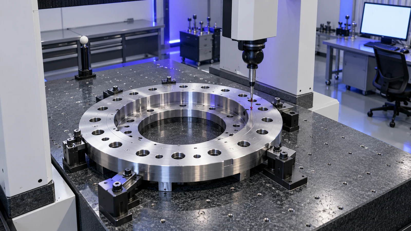
Before final acceptance, verify that the inspection method can reach each feature and that the part is supported without forcing it into a nominal shape. A coordinate measuring approach may be suitable for complex patterns; a dedicated fixture can help with repeated builds if it references controlled datums. The drawing or program inspection plan must state the actual method and limits. Do not infer qualification from a dimensional report alone.
Keep material and revision traceability with the inspection results. If a hole pattern is modified, record the drawing revision and the disposition of previous parts. If the plate has a coating or conversion treatment, note whether measurements were taken before or after that step. This turns the report into useful configuration evidence rather than a file disconnected from the delivered component.
Use a staged build to reduce integration surprises
A low-risk sequence can separate questions. First, use a model or simplified plate to review envelope, orientation, and tool access. Next, produce a machined prototype that represents the important interfaces and material condition for the planned check. Finally, build to the program’s released requirements and acceptance plan. Each stage should have a stated purpose and a clear list of what it does not prove.
For the first adapter build, prepare a mating-interface checklist: bus pattern, payload pattern, clocking, fastener access, interface height, connector clearances, lifting or handling needs, and inspection datums. Review it with the design, manufacturing, and integration teams. If the physical fit test reveals a conflict, document the exact revision and interface involved before changing the part or the mating hardware.
A payload adapter plate succeeds when its interfaces are unambiguous, machinable, inspectable, and compatible with the real assembly sequence. Coordinating those decisions early helps reduce rework and makes the manufacturing record easier to evaluate without overstating what a prototype or dimensional inspection can establish.
Integration questions worth answering early
Does a bolt pattern alone define the adapter interface?
No. Orientation, datum planes, interface height, fastener access, keep-out zones, and connector or harness clearances may also determine whether the payload can be integrated.
Can a prototype prove launch readiness?
Only tests and evidence defined by the approved program can address that question. A fit-check or machining prototype can answer its stated geometry or assembly question, not replace qualification.
Should surface treatment happen before final inspection?
The sequence depends on the drawing and which characteristics treatment can affect. Define whether critical dimensions and contact surfaces are accepted before treatment, after treatment, or at both stages.

