


Read the sealing interface, not just the bolt pattern
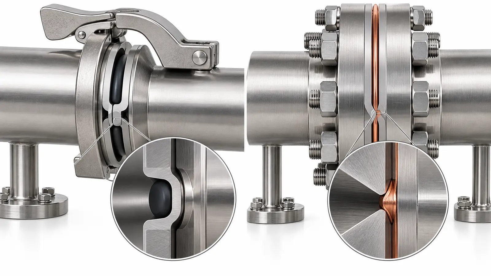
A flange’s outside shape can be misleading. Start with the joint section: does it compress an elastomer carried on a centering ring, or does a knife edge deform a metal gasket? Then identify the nominal size, mating profile and fastening arrangement.
A bolt circle that looks close is not evidence of compatibility. Nominal bore, outside diameter, gasket dimensions and the reference standard must be checked together. Mixed metric and inch descriptions are especially easy to misread when a catalog uses flange outside diameter while a drawing uses nominal tube size.
In semiconductor tools, this interface review belongs alongside the selection of vacuum-side equipment components. The port must support its mechanical function without obstructing wafer motion, service access or the intended pumping path.
Record the flange designation and a supplier or standard drawing reference on the interface control drawing. A photograph is useful for identification, but insufficient for releasing a custom mating part.
Four familiar flange arrangements at a glance
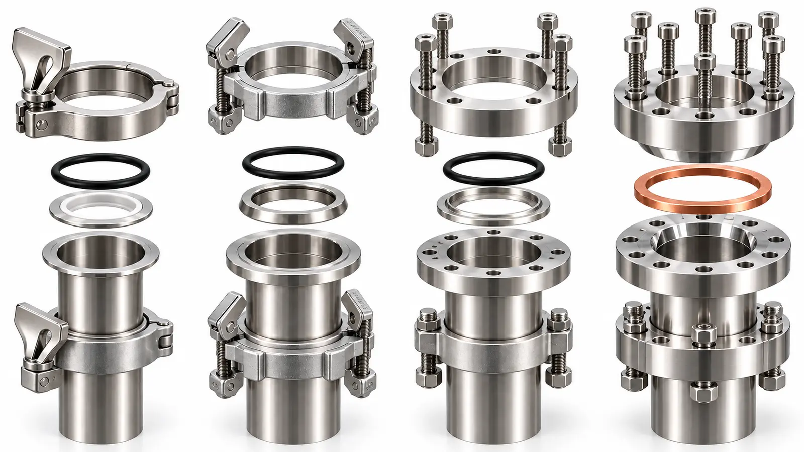
| Family | Usual sealing principle | How it is retained | Typical selection driver |
|---|---|---|---|
| KF / QF | Elastomer O-ring on a centering assembly | Quick clamp around the flange backs | Compact serviceable vacuum connections |
| ISO-K | Elastomer sealing assembly | Claw clamps | Larger connections with suitable clamp access |
| ISO-F | Elastomer sealing assembly | Bolts through the flange | Bolted retention for larger interfaces |
| CF | Metal gasket compressed by knife edges | Bolted joint | Compatible bakeable, low-gas-load vacuum assemblies |
El Kurt J. Lesker flange selection guide distinguishes these families and their sealing approaches. Temperature and pressure capability must come from the selected component and seal specifications; the family name alone is not a complete rating.
KF: convenient does not mean load-bearing
A quick clamp makes a small connection accessible, but the line and attached device still need appropriate support. Avoid using the joint to pull misaligned piping into position or carry the bending load of unsupported equipment.
ISO-K and ISO-F: plan the access envelope
Choose between clamp and bolt arrangements with installation space in mind. Include the tool swing, the route for removing the seal assembly and the mass of the part being disconnected. Similar nominal sizes do not authorize arbitrary mixing of hardware.
CF: protect the feature that makes the seal
The knife edge and gasket form the functional interface. Damage, contamination or an unsuitable gasket can defeat the joint. Follow the component supplier’s assembly sequence and gasket replacement instructions; do not treat a previously compressed metal gasket like a reusable elastomer centering ring.
Let the duty cycle narrow the choice
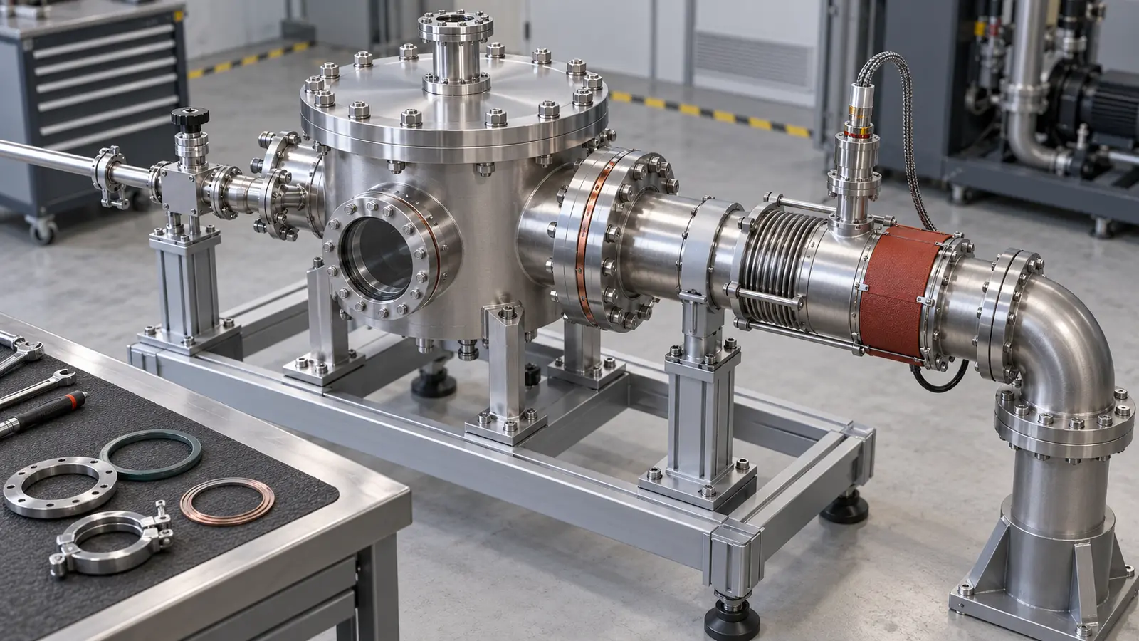
A frequently serviced foreline, a large pump port and a rarely opened hot diagnostic port need not share one flange family. Uniformity can simplify spares, but imposing a single connection style everywhere can make maintenance or thermal qualification harder.
- Establish the gas and cleanliness requirements. Decide whether the proposed seal material and exposed area are acceptable.
- Define the temperature envelope. Include conditioning, cleaning and local heating, not only normal operation.
- Count interventions. Determine how often the joint will be opened and what seal replacement is expected.
- Check mechanical loading. Assess attached mass, bending moments, movement and the support arrangement.
- Confirm the available installation space. Model the real clamps, bolts and tools rather than idealized cylinders.
The result may be a mixed interface architecture. A semiconductor transfer tool can use one family for a gauge, another for a pumping connection and a custom sealed opening for wafer transfer. The design objective is compatible performance at each connection, not a visually uniform set of ports.
Do not assume that a vacuum connection is suitable for positive pressure. Any pressurized cleaning, purge or test condition needs a separately reviewed rating and restraint arrangement.
Custom adapters create a second design problem
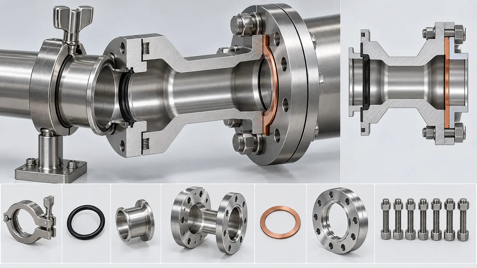
An adapter solves a geometric mismatch while adding length, another seal and another potential alignment error. The useful adapter is not merely the shortest route between two bolt patterns. It must preserve the needed flow path and provide access for assembly and inspection.
Before releasing a CNC-machined flange adapter, identify the controlled face, concentricity or position requirement, mating clearances, sealing profile and fastener thread details. Keep critical geometry tied to functional datums.
For a welded neck or transition, plan joint access and final face machining. For a machined adapter, review the minimum wall between intersecting bores and bolt holes. A tapped hole must not accidentally break into the vacuum space or leave an unplanned trapped volume behind a screw.
Aluminum-to-stainless transitions also need thermal-expansion and joining review. A metal-gasket interface cannot be reproduced in a different alloy merely by copying its visible geometry. Hardness, coating, knife-edge construction and the chosen transition method can be part of the qualified design.
Jucheng Precision’s role can include custom adapters, mounting plates and machined housings made to approved interface drawings. Standard bought-in flange hardware should retain its identified specification; an unqualified custom equivalent should not be described as interchangeable.
An assembly check that catches expensive mistakes
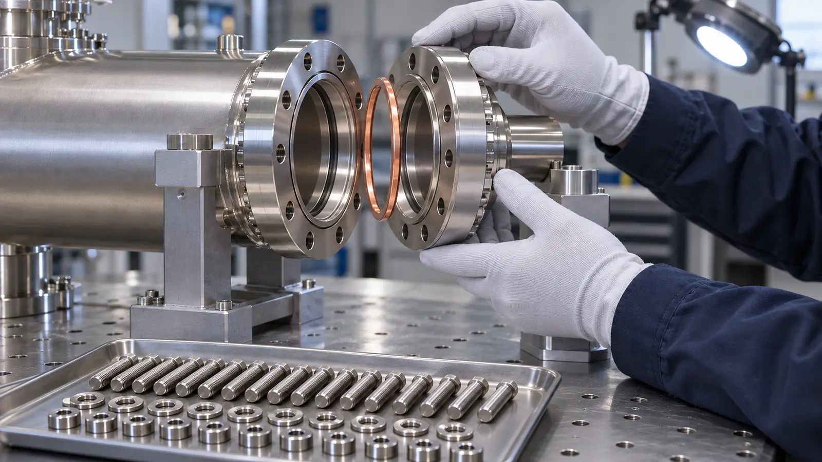
- Confirm both mating parts against the same interface designation and dimensions.
- Inspect the seal, knife edges or elastomer contact faces under suitable lighting.
- Remove particles using the approved cleaning procedure; keep abrasive debris away from the joint.
- Support the connected device so hardware is not used to correct gross misalignment.
- Install the specified centering assembly or gasket, with the supplier’s prescribed hardware and sequence.
- Verify the assembled joint under the agreed test conditions, then record the result and configuration.
The inspection method should reflect what can actually fail. Measuring flange diameter does not reveal a damaged knife edge, and a successful room-temperature assembly does not establish behavior through a thermal cycle.
For repeat builds, retain the relevant interface drawing, approved hardware list and test record with the semiconductor assembly documentation. This helps distinguish a changed component from an installation error when a later unit behaves differently.
Can KF and CF parts connect directly?
No. They use different mating and sealing arrangements. A purpose-designed adapter is needed, and the assembled system remains limited by all of its components, including any elastomer seals.
Does installing CF flanges make the entire chamber UHV-ready?
No. Materials, internal construction, cleaning, seals elsewhere in the system and the available pumping arrangement still matter. A flange choice removes only one part of the gas-load and interface problem.
Is a rotatable flange a substitute for correct port alignment?
It can help align a compatible bolt pattern during assembly. It does not correct an incorrectly positioned bore, an angled port axis or excessive mechanical loading.

