


Start with the symptom and the test boundary
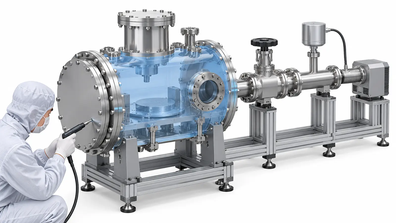
First define what is under test. A bare machined chamber, a chamber fitted with blanking plates and a complete module with valves, gauges and feedthroughs are different test objects. A result from one configuration does not automatically apply to the others.
| Symptom | Possibilities to separate | First useful action |
|---|---|---|
| Pressure stalls during pump-down | Leakage, gas release, restriction or pumping-system issue | Check configuration and compare with an appropriate known baseline |
| Pressure rises after isolation | Leakage, desorption, permeation or trapped gas | Record volume, temperature and the pressure-time curve |
| Failure appears after maintenance | Seal damage, contamination, changed hardware or assembly error | Inspect recently disturbed interfaces first |
| Result changes after heating | Thermal movement, changed gas release or seal behavior | Compare controlled cold and hot test conditions |
In a semiconductor chamber, a long evacuation time can affect throughput even if no discrete external leak is found. Keep pump-down performance and leak-rate acceptance as separate requirements.
Document all temporary items: blanking flanges, hoses, valves, gauge heads and the detector connection. Otherwise a leaking test fixture can be mistaken for a defective chamber body, or a temporary high-conductance connection can hide a limitation of the production installation.
Use pressure rise to measure total gas load
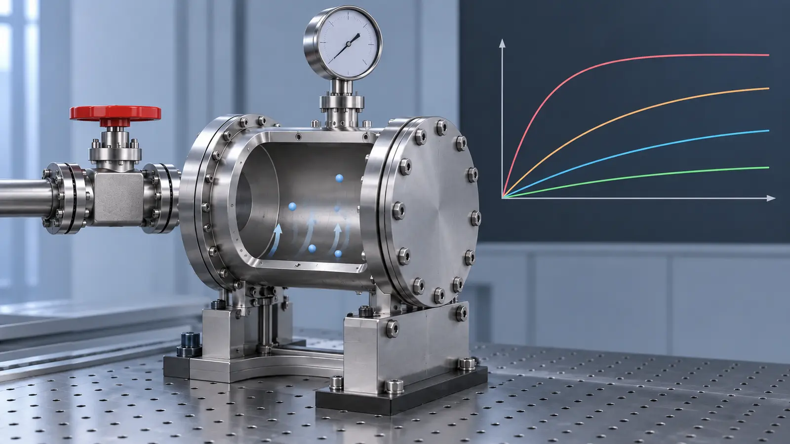
For a stable, isolated volume, the approximate gas throughput is Q = V × Δp / Δt. If V is in liters, pressure in mbar and time in seconds, Q is in mbar·L/s. This is a useful screening relationship, not proof that the calculated flow entered through an external hole.
Illustrative calculation: a 10 L isolated volume rises by 2 × 10⁻⁴ mbar in 100 seconds. The apparent gas load is 2 × 10⁻⁵ mbar·L/s. The example describes total observed gas input under the assumed conditions; it is not a recommended pass/fail limit.
Leybold’s discussion of pressure-rise and pressure-drop tests explains the difficulty of separating leakage from gas evolved by the chamber walls. Even a nearly linear pressure rise over a short interval can be misleading.
Keep the conditions comparable
Record evacuation duration before isolation, effective isolated volume, measurement interval, temperature and gauge type. Temperature changes and gauge behavior can distort the comparison. Use an instrument suitable for the pressure range and gas conditions rather than extrapolating a single sensor across every regime.
Repeated tests after controlled conditioning can reveal a changing gas-release contribution. They do not eliminate the need to locate a suspected physical leak. If the acceptance specification calls for a helium leak rate, a pressure-rise calculation cannot silently replace that test.
Locate a leak without flooding the evidence
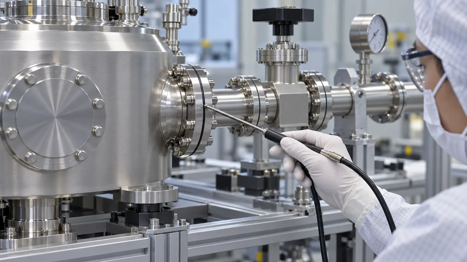
Helium mass-spectrometer testing can detect tracer gas entering an evacuated test object and help localize a leak. The exact procedure depends on the instrument, connection, object volume and required sensitivity.
- Confirm readiness. Follow the detector’s operating procedure and verify response using an appropriate calibrated leak or specified reference method.
- Establish background. Let the connected system reach a stable condition before introducing tracer gas.
- Inspect one area at a time. Apply controlled tracer exposure to a defined joint or feature rather than flooding the entire assembly.
- Allow for response and recovery. A long connection or restrictive path can delay the signal. Move on only when the observation is interpretable.
- Confirm the suspected location. Repeat the exposure under controlled conditions and compare with adjacent areas.
- Retest after the approved corrective action. Record both the original finding and the final configuration.
Large amounts of helium can elevate the background and make later observations difficult. Elastomer permeation can also complicate interpretation. A delayed response is not automatically a local hole at the point most recently sprayed.
For instrument-level setup and precautions, follow the detector manufacturer’s instructions. Leybold’s helium leak-detection overview describes the role of helium detection in locating vacuum leaks. Never introduce an unapproved positive-pressure test into hardware designed only for vacuum.
Inspect the manufactured feature behind the signal
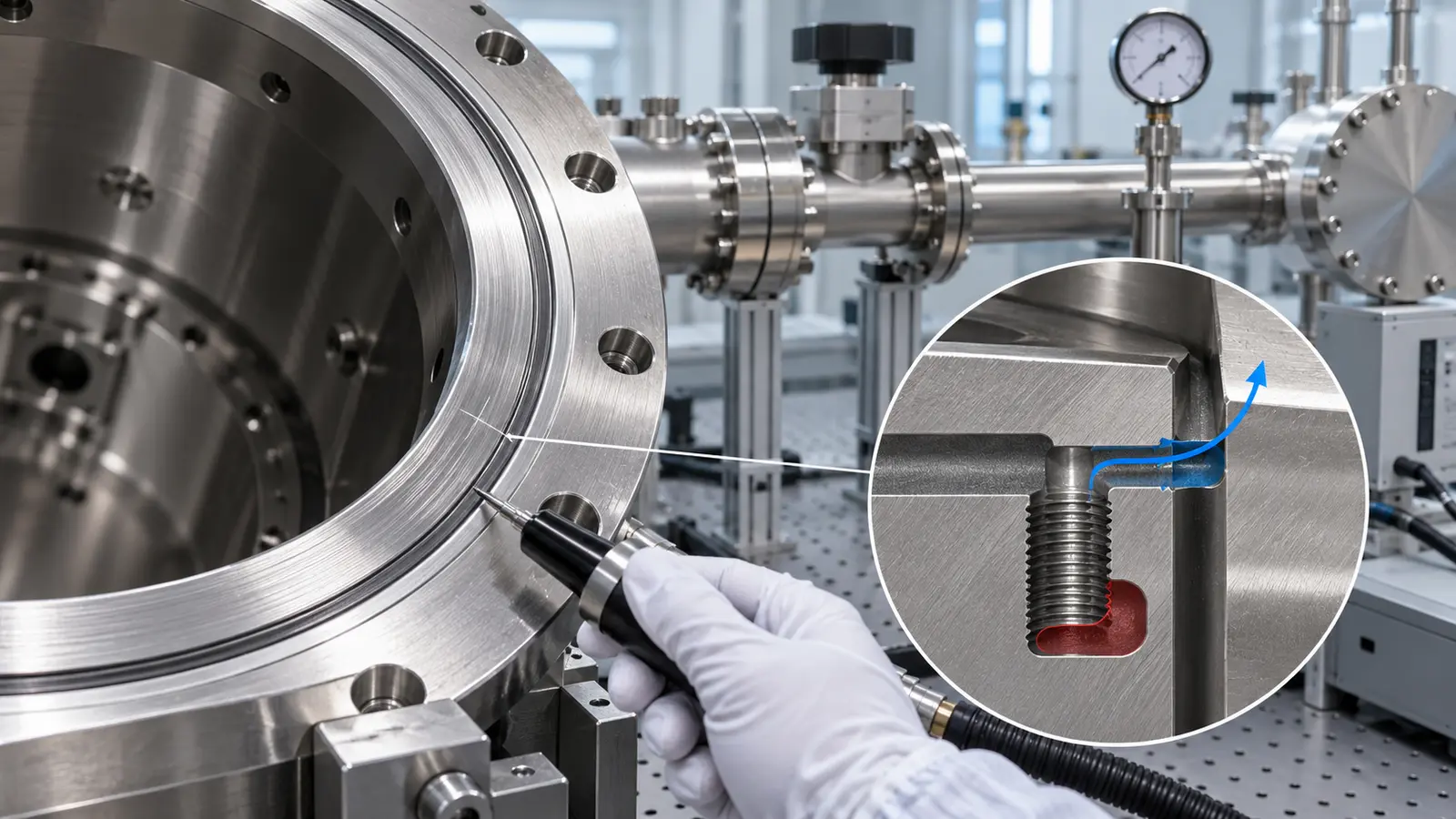
Once a location is repeatable, examine the feature rather than immediately adding sealant. A leak near a fastener can originate from a through-hole, a damaged sealing land, a porous joint or an unintended intersection with an internal passage.
Machined faces and O-ring glands
Check for scratches crossing the seal, particles under the ring, local face movement, burrs and incorrect groove dimensions. Review the actual assembled gland height rather than considering groove depth in isolation. Repeatedly increasing torque can distort the component or damage threads without correcting the original defect.
Welds and intersecting passages
A weld-related indication needs disposition against the approved repair procedure. A blind pocket or partly enclosed joint can instead create a virtual leak by slowly releasing trapped gas. That calls for construction and evacuation-path review, not a search for an external opening alone.
For custom parts made through CNC milling and turning, the corrective drawing may need explicit limits on hole depth, passage intersections, seal-face defects or inspection access. Link the finding to a feature and revision so the same failure is not repeated in the next batch.
Write an acceptance record another engineer can reproduce
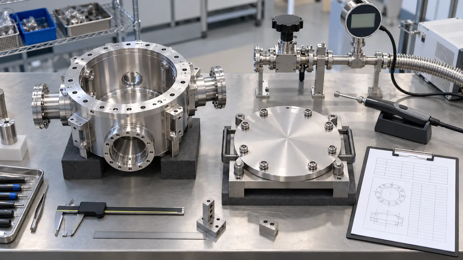
“Leak tested: pass” is not enough to interpret a vacuum chamber leak test. A useful record identifies what was tested, under which conditions, with what measurement capability and against which requirement.
| Record item | Why it matters |
|---|---|
| Part identification and drawing revision | Connects the result to the delivered configuration |
| Assembly, seals and temporary fixtures | Defines the tested pressure boundary |
| Method, tracer gas and pressure conditions | Makes results technically comparable |
| Instrument identification and verification | Establishes the measurement basis |
| Background, response conditions and result | Shows whether the signal was interpretable |
| Acceptance limit and units | Prevents an undefined pass/fail judgment |
| Repair and retest history | Preserves the disposition trail |
Agree the requirement before requesting a quotation. A component supplier and equipment integrator may reasonably own different test stages. Jucheng Precision can review the manufacturing and inspection scope for custom chamber parts; specialist leak-test capability, method and acceptance conditions should be confirmed for the project rather than assumed from general machining capability.
The test record should accompany the dimensional and surface requirements described in semiconductor component quality planning. Leak tightness does not establish particle cleanliness, chemical compatibility or successful wafer processing.
Interpreting difficult results
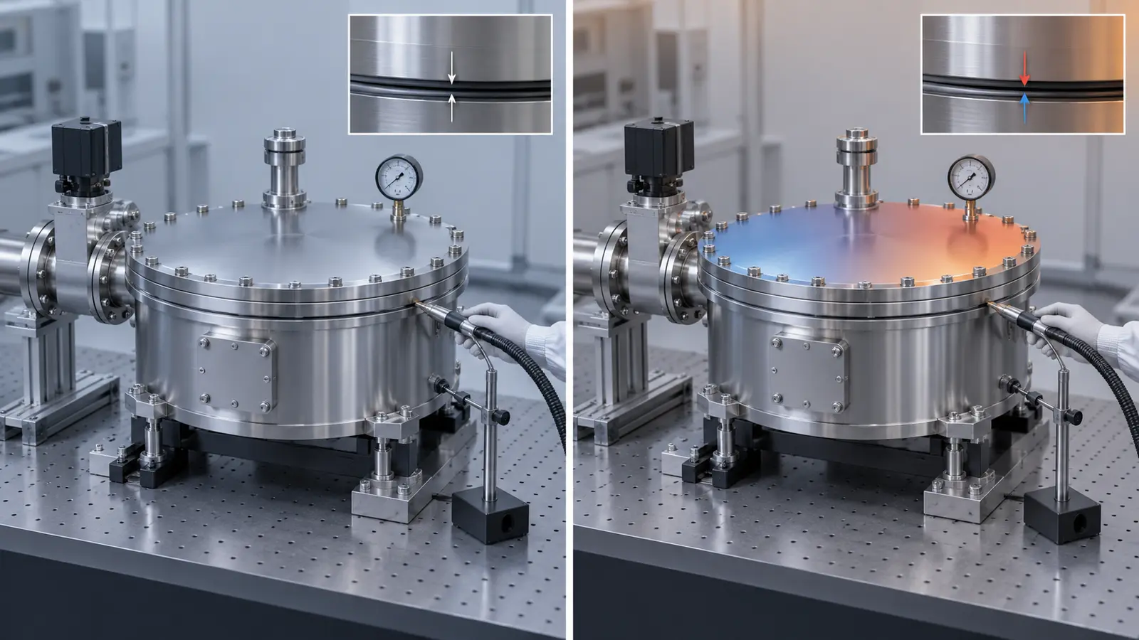
The chamber passes cold but fails hot. Where should the investigation start?
Compare the temperature distribution, seal compound limits, joint movement and test background between conditions. Thermal expansion may change the interface, while heating also changes gas release. Reproduce the agreed operating condition before choosing a mechanical repair.
The pressure-rise test fails, but helium testing finds no location. Is the chamber acceptable?
Not automatically. Investigate gas release, permeation, trapped volumes, method sensitivity and the tested configuration. The two methods measure different things. Acceptance depends on the requirement, not on choosing whichever result looks better.
Can a leak-rate number be compared without its units?
No. Gas species, pressure conditions and units matter. Keep the original units in the record and use a documented conversion when needed. A number copied from a detector display without context is not a transferable specification.
Final distinction: a leak test establishes performance under a defined test. Reliable semiconductor equipment also needs appropriate materials, controlled cleaning, stable mechanics and repeatable assembly. Treat the test as one piece of evidence, not a certificate for the whole process.

