


An aircraft heat exchanger transfers energy between two fluid streams or between a fluid and the surrounding air while meeting a constrained envelope for mass, pressure loss, durability and integration. The part cannot be designed in isolation: the heat source, coolant loop, available airflow, mounting structure and downstream controls determine what an acceptable exchanger looks like. This component-level view complements our aerospace prototyping and manufacturing overview.
Engineers often begin with a core concept, but the better starting point is the thermal loop. What fluid enters each side? What heat must be moved in each operating condition? What airflow or pumping capacity is available? Where can the unit be mounted, drained, inspected and removed? Without these inputs, a compact core may still create unacceptable pressure loss or installation problems.
Contents
- The exchanger belongs to a loop, not a parts list
- Architecture changes the trade space
- Airflow, coolant and pressure boundaries
- Manufacturing choices shape the core
- Materials and joining affect life-cycle behavior
- Plan for verification and service from the start
- Frequently asked questions
The exchanger belongs to a loop, not a parts list
A heat exchanger moves heat from a warmer stream to a cooler one through a separating surface. On aircraft, the two streams and the ultimate heat sink depend on the system: possible arrangements include air-to-air and liquid-to-air heat transfer, among others. The exchanger’s boundary conditions therefore come from system architecture rather than from the component name.
Write down the operating cases before selecting geometry. Consider the expected inlet temperatures, flow rates, fluid properties, ambient conditions, heat load and allowable outlet conditions. A design point may not capture transient or off-design states. The thermal team should identify which cases govern core size, while the systems team checks that fans, pumps, ducts and controls can support the resulting pressure losses.
Heat transfer area is only one part of the problem. Increasing fin density or adding a longer flow path may improve heat exchange in some conditions, but it can also affect pressure drop, fouling sensitivity, cleaning and mass. A more efficient-looking core is not a better aircraft component if the system cannot move fluid through it or if the pressure penalty undermines the larger loop.
NASA’s work on aircraft heat-exchanger sizing and performance illustrates why heat rejection, air and coolant flow, geometry and operating points are evaluated together. The useful lesson is methodological: state the boundary conditions, then compare architectures against them.
Architecture changes the trade space
Different exchanger constructions expose different manufacturing and integration constraints. A plate-fin core can offer a compact arrangement of alternating passages; a tube-based design may provide a different route for fluid separation and service; a liquid cold plate handles heat at a mounted equipment interface and normally relies on a broader loop to reject that heat elsewhere. These are not interchangeable simply because each moves thermal energy.
| Architecture family | What it can offer | What the review must address |
|---|---|---|
| Plate-fin core | Large heat-transfer area in a compact package | Fin geometry, joining, flow distribution and inspection of internal passages |
| Tube or tube-fin assembly | Distinct fluid paths and adaptable external routing | Tube joints, support, vibration, service access and leak boundaries |
| Liquid cold plate | Direct interface for electronics or another mounted heat source | Contact quality, coolant passages, mounting and connection to a separate heat sink |
| System-level exchanger module | Can combine core, ducts, frame and connections | Packaging, access, airflow management and interfaces to the aircraft structure |
The table is a conceptual aid, not a prescribed selection. The aircraft program’s environmental, thermal and structural requirements control the choice. NASA’s aerodynamic heat-exchanger research has also explored optimizing core shape for mass and drag, underscoring that an exchanger interacts with its airframe installation rather than operating as a free-standing textbook core.
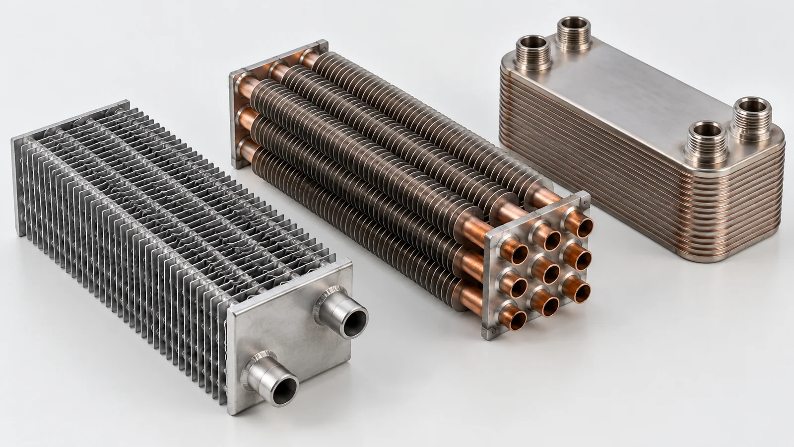
Design reviews should state why an architecture was chosen, which alternatives were rejected and what assumptions remain open. That record helps manufacturing and procurement understand the priorities when a later change affects the package or production method.
Airflow, coolant and pressure boundaries
Air-side and fluid-side interfaces should be modeled with the surrounding installation. The air inlet and outlet need clear paths; nearby structure, fairings or equipment may alter local flow. On the liquid side, ports, fittings, drain or vent provisions and line routing determine whether the core can be installed and serviced without interference.
Define the pressure boundary explicitly. Identify which walls, joints, tubes, headers, covers and connections separate the streams. A leak path can mix fluids or release fluid outside the intended route, so a drawing should show joint locations and the boundary that testing must cover. Acceptance limits and test conditions must come from the controlling system requirements; a generic pressure value should not be invented in a blog article.
Pressure loss is an integration issue as much as a core issue. The selected exchanger consumes part of the available fan or pump capability. If the system team has a limited pressure budget, the design should track how much is assigned to the core, fittings, ducts and downstream elements. Any design change to channel size or fin density can alter the balance.
Consider maintainability in the same envelope. Can technicians access connections? Can the assembly be removed without disturbing adjacent systems? Does the design provide a way to inspect or clean surfaces that may accumulate debris? These questions often expose packaging conflicts while the model is still easy to change.
Manufacturing choices shape the core
Core geometry must be compatible with the selected production route. Thin fins, closely spaced passages, long joints and multiple layers can create requirements for forming, stacking, brazing, bonding or other joining methods. The sequence can affect dimensional stability and whether internal passages remain open. For a machined interface plate or header, access, wall thickness and datum strategy matter as much as the nominal outline.
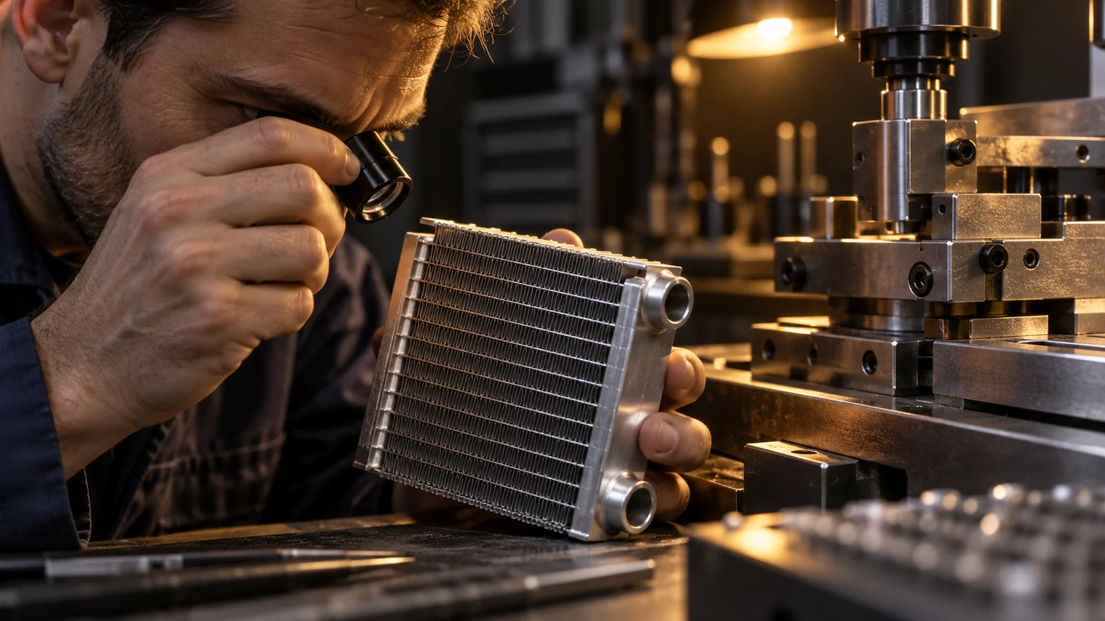
Use design-for-manufacturing review to identify the features that are most sensitive to process variation. Ask how the core is located during joining, which surfaces are finish-machined afterward, how the header aligns with the core, and whether the assembly can be inspected without destructive sectioning. If the manufacturing process changes, determine which thermal or structural assumptions need to be re-evaluated.
Prototype intent should be clear. An envelope model can verify packaging; a flow article can support early testing; a production-intent unit should reflect the planned material and joining route when those variables influence performance. Do not treat a visual or dimensional prototype as proof of thermal capacity or leak performance.
For broader process-selection context across machining, sheet metal and other routes, see our aerospace manufacturing processes guide. The right method depends on the exchanger’s core, interfaces and release requirements.
Materials and joining affect life-cycle behavior
Material selection must consider conductivity, density, corrosion environment, fluid compatibility, joining method, mechanical loading and maintenance. Lightweight aluminum alloys appear in many heat-exchanger contexts, while other materials may be selected for specific environments or fluids. The chosen alloy and condition must follow the program specification; a material family alone does not define a safe design.
Joining can dominate performance and durability. A brazed or bonded core requires control of the joining cycle, joint geometry and post-process condition. Dissimilar materials may introduce thermal expansion or corrosion concerns. Surface treatments can protect a part but may change dimensions at a mating interface or influence bonding and sealing.
Include the required material specification, lot identity, condition, joining records and any post-process evidence in the procurement package. Our aerospace materials guide is a broader reference for material tradeoffs; the exchanger design authority must approve the specific material stack and process.
Do not optimize mass by removing material from a wall or support without checking the pressure boundary, stiffness and installation loads. A lighter core that deforms at its connections can create a leak or misalignment problem that outweighs the mass benefit.
Plan for verification and service from the start
A verification plan should connect thermal, dimensional and pressure requirements to distinct evidence. Thermal performance testing needs a controlled setup with known inlet conditions and flow. Leak or pressure testing needs a defined boundary and acceptance criterion. Dimensional inspection should focus on interfaces that determine fit, alignment and sealing.
- Document the test configuration, sensors, fluid and operating point used for thermal evaluation.
- Record the pressure boundary and acceptance criteria for leak or proof testing.
- Inspect mounting, port, duct and seal interfaces against released datums.
- Check that joining and cleaning steps leave the intended internal flow paths open.
- Maintain traceability between the tested unit, drawing revision and material records.
Service planning matters because a heat exchanger may need inspection or cleaning after exposure to its operating environment. The service procedure should not require access that the installed assembly does not provide. If cleaning, flushing or replacement is part of maintenance, show the necessary access and connection points in the design review.
Changes to fin geometry, joining sequence, fluid, coating, inlet condition or packaging can affect the validated configuration. Treat each as a controlled engineering change and determine whether prior evidence remains applicable.
Frequently asked questions
Is an aircraft heat exchanger the same as a cold plate?
No. A cold plate transfers heat from a mounted component into a coolant. A heat exchanger transfers heat between streams or from a fluid to air. They may work in the same thermal loop, but their interfaces and design tasks differ.
Which aircraft heat-exchanger architecture is best?
There is no universal best architecture. Selection depends on heat duty, available airflow or pumping, pressure-loss limits, package, mass, service needs, fluid compatibility and the manufacturing route that can be verified.
What inputs should be available before a design review?
Provide operating cases, inlet conditions, flow rates, heat load, allowable outlet conditions, pressure-loss budget, package and mounting envelope, fluids, environmental requirements and verification needs. Identify assumptions that are not yet approved.

