


An aircraft wing spar is the primary spanwise structural member that carries wing loads into the aircraft structure. Manufacturing planning therefore has to protect more than the outside profile. It must preserve the datum scheme, attachment interfaces, local wall thickness, and inspection access that let the spar fit into a larger wing assembly. The right process depends on the drawing, material condition, part envelope, production quantity, and which features control assembly.
For a machined spar, the central planning question is not simply whether a five-axis machine can reach the geometry. It is whether the chosen blank, locating strategy, and operation sequence can produce the required shape without making the inspection plan or later assembly difficult. This guide focuses on those manufacturing decisions rather than aircraft structural design approval.
Contents
- A spar is a load path, not just a long milled beam
- Freeze datums before choosing the blank
- Choose machining around the load path and geometry
- Where distortion enters the route
- Inspection has to reach the features that matter
- What a supplier needs before quoting
- Frequently asked questions
A spar is a load path, not just a long milled beam
The spar works with ribs, skins, and fittings to transmit loads through the wing. Its flanges, webs, pockets, and attachment points do not have equal manufacturing importance. A shallow pocket may reduce mass, while a fastener row or root interface may govern location and fit. Treating every surface as an equally critical machining target can add cost without improving the assembly.
Before process selection, the engineering team should identify the functional interfaces and the surfaces used to establish position. A drawing datum may represent a real mating surface, a tooling interface, or a coordinate reference used by inspection. Those roles need to be understood before stock is selected or a fixture is designed.
This is why spar procurement should be connected to the wider Aviation and Aerospace manufacturing context, not treated as an isolated shape. The parent page helps frame how prototype, part manufacturing, and process selection relate across the program.
Freeze datums before choosing the blank
Long, lightweight parts are sensitive to how they are supported. If a blank is clamped aggressively to make it appear flat, releasing the clamps can reveal springback. If a fixture locates from a surface that will later be removed, the next setup may not repeat the first. Datum planning should therefore follow the drawing’s functional relationships from initial stock through finishing and final inspection.
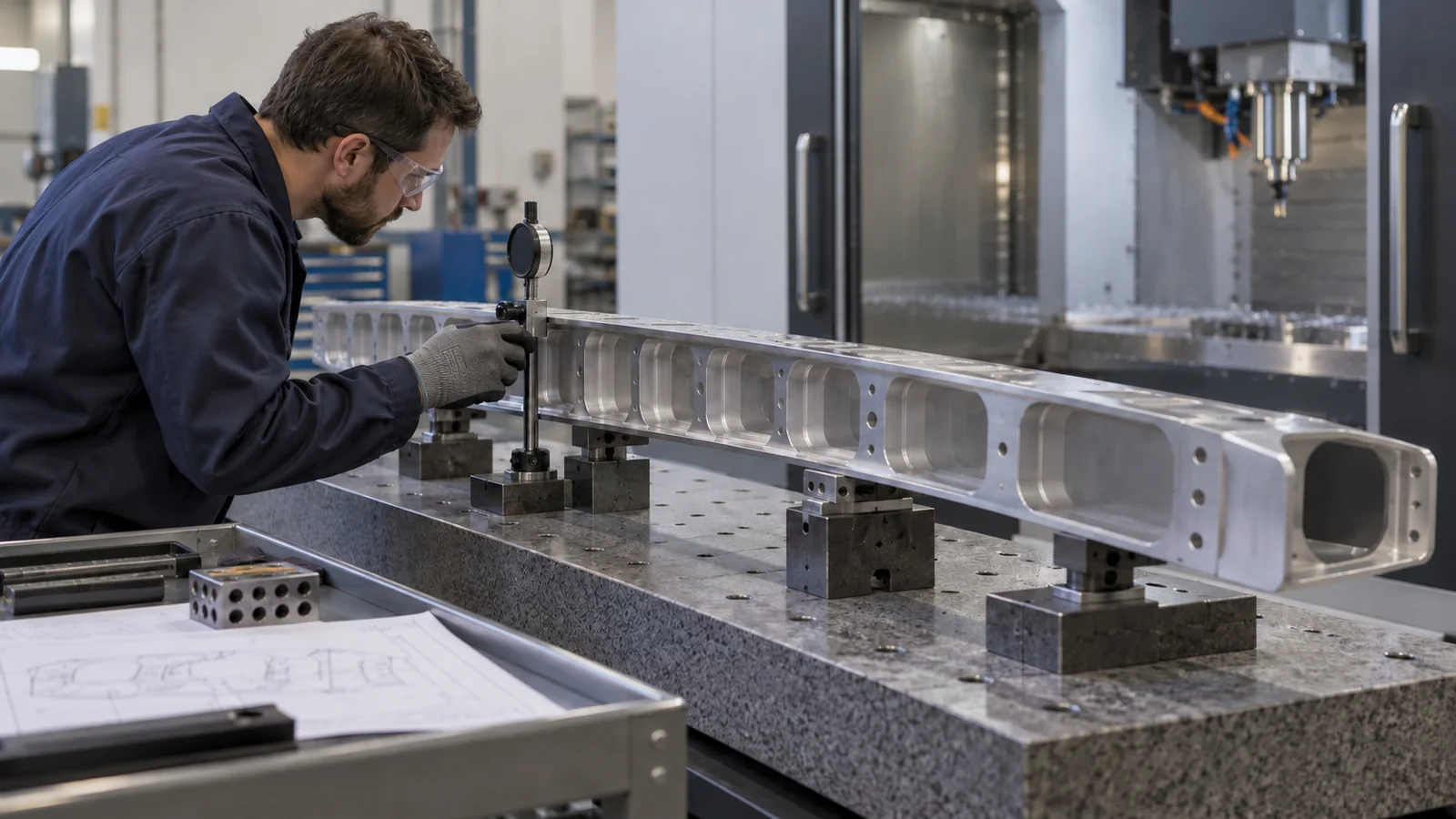
For each setup, record which surfaces locate the part, which features are being cut, and which datums remain available afterward. This simple map exposes a common problem early: a sequence can machine every feature yet still leave no stable reference for the final operation.
Blank selection also affects the route. A near-net or forged blank may reduce material removal but arrive with allowance variation. Plate or billet stock can simplify procurement for a prototype, but may create a large buy-to-fly ratio and more exposure to residual-stress movement. Neither option is universally preferable; the drawing revision, grain requirements, supply route, and lot size decide the tradeoff.
Choose machining around the load path and geometry
Five-axis machining can reduce repositioning for compound geometry, but axis count alone does not guarantee accuracy. The workholding plan still needs a stable support condition, collision-free access, and a way to measure critical interfaces. A long spar may require multiple indexed setups even when the overall route uses five-axis equipment.
| Part condition | Manufacturing implication | Question to resolve |
|---|---|---|
| Long span or large envelope | Support and machine travel influence the setup plan | Can the part be located and checked across its full length? |
| Deep pockets or thin webs | Tool reach and remaining stiffness change during material removal | Which roughing and finishing sequence limits movement? |
| Compound attachment faces | Multiple orientations may be needed to reach all interfaces | Which datum transfer controls the final relationship? |
| Prototype quantity | Flexible fixtures can be more suitable than dedicated tooling | Can setup cost be kept proportionate to the build quantity? |
When geometry requires access from several directions, a documented five-axis or multi-setup plan can reduce ambiguity between programming and inspection. The five-axis CNC machining page is the relevant process reference for parts whose features cannot be reached efficiently from one orientation.
Do not confuse fewer setups with lower risk by default. If a one-setup approach makes support weak or measurement difficult, a carefully controlled second setup may be the more predictable choice.
Where distortion enters the route
Material removal changes the stiffness of a part as the cut progresses. Thin webs and flanges can move when surrounding stock is removed, and a part that is forced against a fixture may relax after unclamping. Tool pressure, heat input, clamp position, and the order in which pockets are opened can all affect the final shape.
A practical plan separates bulk removal from final surface generation. Roughing can leave a controlled allowance, followed by a release or stabilization check when the geometry and material condition justify it. Finishing then references a stable locating scheme rather than relying on the shape created by the roughing clamps. The actual sequence must be validated for the part; a generic “rough, rest, finish” recipe cannot substitute for process evidence.
Questions to settle at design review include whether the part is supported close to the cutting zone, whether clamp forces act through robust areas, and whether thin sections are finished symmetrically. If multiple pieces share a blank or are cut from plate, the orientation and release order can also affect how each part moves.
Inspection has to reach the features that matter
A spar inspection plan should distinguish accessible external surfaces from internal pockets, long profiles, and fastener interfaces. A coordinate measuring machine may be appropriate for selected geometric relationships, while dedicated gauges or calibrated hand tools may suit other checks. The measurement method has to match the feature, tolerance, datum scheme, and required record.
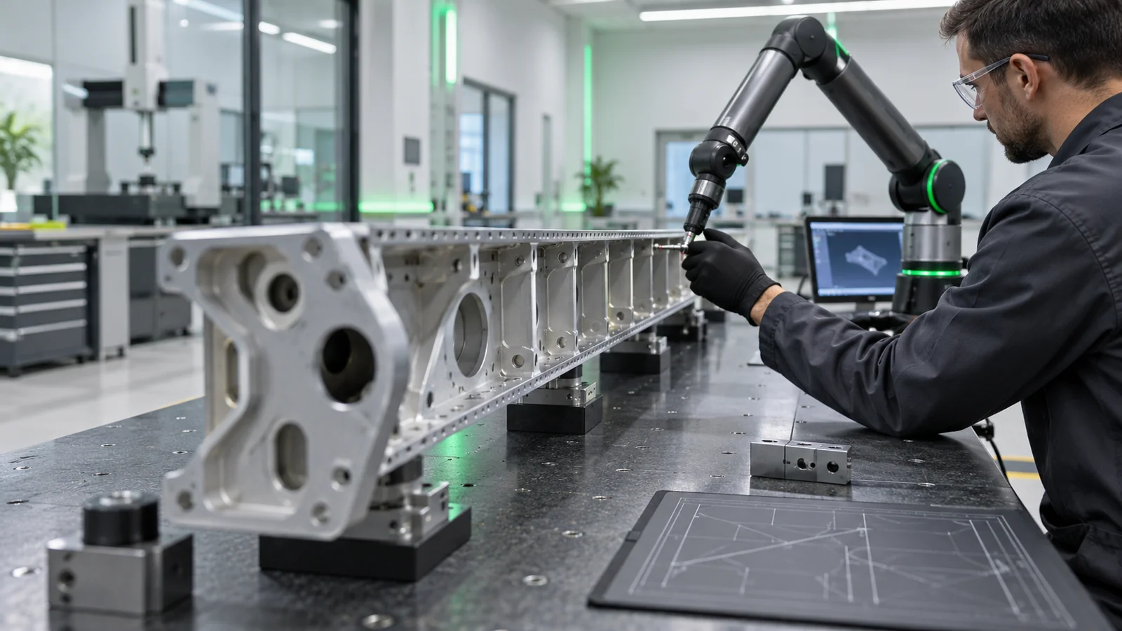
Inspection planning should begin before the final toolpath is complete. A probe path, fixture clearance, or optical line of sight may be blocked by a wall or clamp. If a feature cannot be measured after the part is finished, the route needs an in-process check or a revised access plan. That is an engineering planning decision, not an excuse to infer a result from a machine program.
For a first article or prototype, the inspection package should identify drawing revision, characteristic, datum reference, method, and result format. This makes it easier for the buyer and supplier to discuss a discrepancy without confusing a measurement setup issue with a manufacturing issue.
What a supplier needs before quoting
A useful RFQ package includes the current drawing or model, material and temper, quantity, finish requirements, critical-to-function characteristics, inspection expectations, and any program-specific documentation. If the drawing includes a long profile or thin-wall region, mark the surfaces that must remain aligned with the assembly datums. Do not replace the controlled drawing with screenshots or a list of desired tolerances.
For early development, separate what is fixed from what can still change. A prototype request may allow a non-flight article or a temporary inspection plan, but it should state that status explicitly. A supplier cannot infer whether a sample is for fit evaluation, process learning, or qualification work from the word “prototype.”
Ask for clarification when a tolerance is tighter than the functional need appears to require, when two datums conflict, or when a feature is inaccessible to normal inspection. Resolving those issues before material is committed reduces avoidable rework while keeping design authority with the responsible engineering organization.
Frequently asked questions
Is every aircraft wing spar made from one machined billet?
No. The route depends on aircraft design, material system, size, program requirements, and supplier capability. Machined metallic parts are one route; formed or assembled structures and composite structures may follow different processes.
Does five-axis machining remove the need for a fixture plan?
No. Five-axis motion improves tool access, but workholding still controls support, datum transfer, vibration, and inspection access. Those decisions must be planned for the actual geometry.
What should be checked before a spar prototype is ordered?
Confirm the drawing revision, material condition, quantity, functional interfaces, prototype purpose, inspection method, and which features are allowed to change. The prototype status should not be mistaken for production or flight approval.
Can a supplier choose a tighter tolerance to improve fit?
Not without agreement from the responsible design authority. A tighter tolerance can add cost and inspection burden, and it may not resolve a datum or assembly problem.
A wing spar quote becomes more reliable when the buyer and manufacturer agree on datums, blank condition, material-removal sequence, and inspection access before machining begins. That conversation creates a traceable manufacturing plan without implying that a prototype alone proves structural suitability.

