


A satellite optical baffle tube is a light-control component, not simply a cylindrical spacer around a telescope. Its job is to keep unwanted light from reaching the detector while staying clear of the intended field of view, surviving the spacecraft environment, and fitting the surrounding optical assembly. That makes the key manufacturing question geometric: can the internal profile, surface condition, interfaces, and mounting features be produced and inspected without introducing glare paths or obstructing useful rays?
The answer depends on the optical prescription and stray-light analysis. The machine shop should not invent vane spacing, wall angles, or a blackening requirement from a generic baffle concept. Those values must come from the optical and systems teams. Manufacturing can, however, help expose where the design needs clearer datums, tool access, inspection access, and finish definitions before the part is released.
Contents
- Begin with the stray-light path
- Turn optical intent into a machinable profile
- Geometry traps inside a long tube
- Select a material with the finish in mind
- Choose a process for the internal features
- Inspect what can actually affect stray light
- Release the part with optical context
Begin with the stray-light path
Before detailing the tube, identify the source regions that the baffle must block and the field angles that must remain unobstructed. The optical team may define a sequence of knife edges, vanes, or a contoured interior. Each feature is useful only in relation to the rays it is intended to intercept. A visually deep tube can still leave a path for off-axis light if its geometry is not tied to the system analysis.
Ask for the controlled optical model or the derived mechanical interface definition, the clear-aperture envelope, any keep-out zones, and the treatment requirements for interior surfaces. Separate these requirements from cosmetic expectations. A uniform black appearance may be desirable, but it does not alone prove low reflectance at the relevant wavelength or angle.
When the baffle connects to a telescope or sensor assembly, define the mounting datum and optical-axis relationship explicitly. The aerospace prototyping and manufacturing page is relevant to the broader program context; the component drawing itself should remain controlled by the project’s optical and mechanical authorities.
Turn optical intent into a machinable profile
A useful drawing communicates which interior surfaces are functionally critical. A stepped bore, a sequence of annular vanes, or a tapered internal contour can each control stray light differently. If the optical model includes a complex profile, define the transition points, edge radii, and relationship to the axis in a way that a machinist and inspector can reproduce.

Keep the optical axis tied to accessible mechanical references. For example, the mounting face and a precision external diameter may establish the setup, while the internal features are machined concentric to that axis. If the part will be assembled using a flange or pilot, define whether the pilot centers the part or merely provides clearance. Avoid making the supplier infer the intended alignment from a render.
Consider how small edge breaks affect the design. An uncontrolled burr or large radius on a vane can change the effective aperture or create a reflective surface. Specify the edge condition where it matters, and use a general deburring note for noncritical edges. This keeps inspection focused on geometry that influences the optical path.
Geometry traps inside a long tube
Long, narrow internal features are difficult to cut, finish, and inspect. Tool reach can limit cutter stiffness; a slender tool may deflect and leave taper or chatter. A narrow annular groove may trap chips or become inaccessible to a coating process. A thin wall can distort under clamping or after material removal. These are not reasons to avoid a design, but they should be discussed while dimensions are still adjustable.
Review the tube in a section view and ask where the tool enters, how chips escape, which faces support the part, and how the interior can be measured. If a vaned profile cannot be reached with a standard tool, the team may consider segmenting the design, changing vane geometry, or selecting an additive route for an early model. Any redesign must be returned to the optical analysis because a manufacturing convenience can alter stray-light behavior.
Do not hide a difficult internal tolerance in a general note. Identify the controlling diameter, profile, or position characteristic and choose a practical inspection method. A borescope can reveal contamination or visible damage but may not establish dimensional conformance. A CMM, optical comparator, scanning system, or dedicated gauge may be appropriate depending on geometry and acceptance needs.
Select a material with the finish in mind
Material choice affects mass, stiffness, thermal behavior, machinability, and compatibility with the required optical-surface treatment. Aluminum may be attractive for lightweight structures and machining access, while another material may be selected for system-level thermal or structural reasons. The program’s approved-material list and cleanliness controls take precedence over generic material preferences.
Interior finish is a functional requirement, not a paint color. The specification should identify the approved process, coverage area, preparation, masking boundaries, and any post-process inspection or witness requirements. Black coatings, conversion treatments, anodic finishes, or other treatments have different optical, dimensional, and environmental properties. Do not assume that one treatment is interchangeable with another.
Finishing can change dimensions, close small features, leave residue, or alter the edge condition. Provide enough allowance and access for the selected process, and protect critical mounting faces where the specification requires it. A supplier should receive the finish specification and cleanliness expectations before quotation, not after the machined blank is complete.
Choose a process for the internal features
For a simple tube with accessible turned or milled features, CNC machining may provide a direct route from billet or tube stock. A multi-axis setup can reduce datum transfers, but it does not remove the need to plan tool reach and inspection. Review the CNC machining service against the actual internal profile, material, finish, quantity, and inspection package.
For highly intricate vanes or closed internal passages, a prototype made by additive manufacturing can help evaluate packaging and assembly, but its surface texture and dimensional behavior may differ from the eventual optical part. A prototype should be labeled and used for the specific question it can answer—fit, clearance, or assembly—not treated as proof of optical performance unless it uses the required material and finish and is verified accordingly.
Another option is to divide the baffle into sections, machine accessible features separately, and join them using a controlled interface. This can improve tool access but introduces seams, alignment features, and potential light-leak paths. The optical team must assess those effects. Every process route should be evaluated against the required interior geometry and finish, not only purchase price.
Inspect what can actually affect stray light
A balanced inspection plan separates dimensional checks, surface-treatment verification, cleanliness, and optical validation. Dimensional inspection can confirm the profile and datum relationships. Finish records can confirm the approved process was applied. Cleanliness inspection can check for chips, residue, or handling contamination. Only an appropriate optical test or system-level analysis can establish performance against the project’s stray-light requirement.
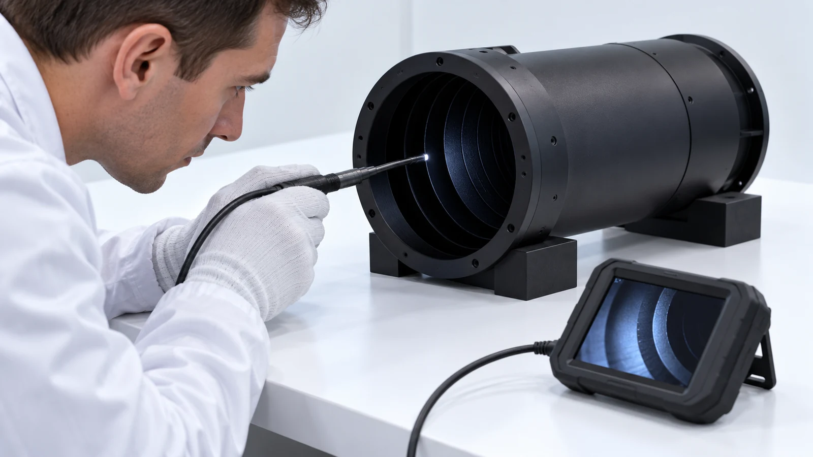
Define access for the inspector. If the narrowest portion cannot be measured with available equipment, decide whether to use a calibrated surrogate, sectioned process coupon, first-article method, or another approved verification. Record the method and its limitation. A photograph of a black interior is not a measurement of reflectance.
For assemblies with multiple baffle sections, record the configuration and orientation used during inspection. A component can meet its own profile while a reversed or rotated installation creates an unwanted path. Keying features, assembly marks, and clear datum references can reduce that risk when permitted by the design authority.
Release the part with optical context
A quotation package should include the 3D model and drawing revision, material and temper, controlled internal profile, datum scheme, finish and masking requirements, cleanliness expectations, inspection characteristics, and quantity. Include a section view or derived interface drawing when it conveys information that is difficult to infer from the solid model. Identify characteristics that are critical to the optical function.
During design review, ask three practical questions: can the selected process reach every required feature; can the specified finish be applied and checked; and can the inspection plan demonstrate the characteristics that matter? If any answer is unclear, resolve it before release. That is more useful than adding generic “high precision” language to a drawing.
For material planning, the aluminum alloy material overview can support an initial conversation about machinability and options, while the project’s approved specification controls the final choice. The manufacturing partner should receive the optical context needed to protect the design without being asked to assume responsibility for the optical prescription.
A baffle is an optical boundary with mechanical interfaces
A satellite optical baffle tube is successful when its interior geometry blocks the intended stray-light paths, its exterior interfaces preserve alignment, and its finish survives the specified environment without compromising dimensions or cleanliness. The fastest route to a reliable part is a shared review among optical, mechanical, manufacturing, and quality teams—before a difficult internal feature becomes a late-stage inspection surprise.

