


Una automotive balance shaft is a rotating engine component that carries deliberately distributed mass to counter selected inertial forces. Its job is defined by the engine’s architecture, not by the shaft in isolation. For a part developer or buyer reviewing a drawing, the practical challenge is to preserve the relationship between the bearing journals, drive feature, thrust faces, and eccentric masses so the shaft can be assembled and checked from a consistent datum scheme.
That relationship matters because balance correction is sensitive to both mass and angular position. A shaft can meet individual diameters yet still be difficult to assemble if its drive interface is clocked incorrectly, or difficult to inspect if the journal axis is not the reference used for the other critical features. The right review therefore starts with the intended load path and assembly datums, then works outward to manufacturing sequence and inspection evidence.
What the balance shaft is designed to cancel
Reciprocating engine components create forces that vary with crank angle. Depending on cylinder arrangement and operating conditions, an engine may use one or more balance shafts to generate an opposing inertial effect. A familiar Lanchester-style arrangement uses a pair of shafts rotating in opposite directions; the exact number, speed ratio, and counterweight geometry depend on the engine design. The mechanism is not a universal cure for every vibration source: combustion variation, mounts, crankshaft behavior, and other rotating assemblies remain separate contributors.
Research on engine balancing treats the counterweight geometry and its position as part of a system that includes the crankshaft and bearing arrangement. That is why a drawing should make the shaft’s functional interfaces explicit. A useful design review asks which force or moment the component is intended to address, how its phase is established during assembly, and which surfaces locate it relative to the drive. It should not infer a target balance value from a generic article or a visually similar engine.
For a prototype, the buyer should provide the current drawing revision, assembly orientation, gear or chain interface details, and any required balance or runout acceptance criteria. If a value is not defined, the manufacturer should request clarification rather than substitute a shop convention. Component geometry can support an assembly’s balance plan, but it cannot establish the complete engine’s vibration performance by itself.
Read the journals and drive features as one datum system
The bearing journals establish the rotational axis. Their diameter, spacing, surface finish, and relationship to thrust faces affect how the shaft locates in its supports. The drive gear, sprocket seat, keyway, spline, or other drive interface then transfers torque and establishes angular phase. Counterweight lobes or eccentric features must be related to that same axis and clocking reference. Treating every feature as an isolated dimension can hide the chain of relationships that actually matters at assembly.
A drawing review should identify a primary rotational datum and show how the remaining journals, shoulders, and drive features are controlled from it. Where a phase angle is important, the drawing needs a clear angular reference: a keyway centerline, a specified tooth, a machined flat, or another unambiguous feature. The chosen datum must also be physically accessible for inspection. If the setup used to machine the journals differs from the setup used to cut the drive feature, the process plan needs a reliable way to preserve their relationship.
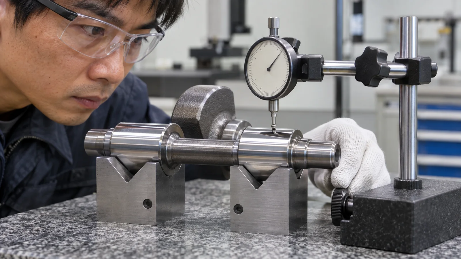
For context on adjacent rotating engine geometry, compare the datum logic in camshaft lobes, journals, and timing datums. A balance shaft has a different function and geometry, but both parts illustrate why an axis and timing reference should be explicit before machining or inspection begins.
Sequence the work around the functional axis
The best sequence depends on the blank, material condition, feature access, and required production route. A prototype may begin with a turned blank to establish the journal axis and shoulders, followed by milling or another suitable operation for drive details and mass features. A production design may use forming, forging, casting, or a combination before finish machining. These are alternatives to evaluate, not claims about a single preferred route for every balance shaft.
When turning establishes the bearing axis, later operations should reference that axis through appropriate workholding or a documented transfer datum. If a shaft is repositioned for milling, the setup should control rotation about the axis as well as axial position. A keyway or flat may be used as an angular locator only when the drawing and process plan define it as such. Workholding pressure also deserves review: a slender shaft can deflect under clamping and recover after release, making in-process readings differ from the free-state result.
For a prototype order, it is useful to separate critical-to-function features from convenience geometry. Journals, thrust faces, drive fits, and mass-position features usually deserve early agreement on measurement method and acceptance criteria. Nonfunctional reliefs or cosmetic edges should not consume the same inspection effort unless the drawing assigns them a requirement. A capability discussion can then focus on the actual geometry and material supplied, rather than presume that one machining operation solves every feature.
Keep mass correction separate from dimensional acceptance
Dimensional inspection verifies that the part matches the drawing; balancing verifies mass distribution under a specified fixture, speed, and correction method. Those activities answer different questions. A journal may be within its size tolerance while a residual unbalance remains, and a balancing operation cannot correct an incorrectly located bearing seat or a misclocked drive interface. The inspection plan should state whether balancing is required at the component level, at assembly level, or by the engine integrator.
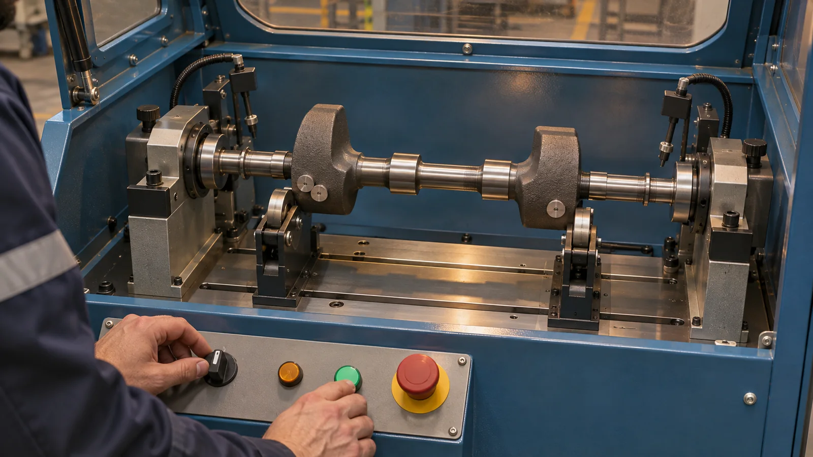
If the drawing calls for material removal or correction features on an automotive balance shaft, define the permitted correction zones and limits before machining. Unplanned drilling or grinding can weaken a section, alter a coating, or change a feature that is not intended to be adjusted. If a balancing report is required, specify the unit, reference axis, fixture, measurement condition, and report format. Without those details, two suppliers may return results that cannot be compared.
Where the balance shaft is evaluated as part of a larger assembly, preserve traceability between the component revision and the assembly configuration. Record which drive gear, fastener, and mating parts were used for any assembly-level check. This does not turn a prototype inspection into engine validation; it simply makes the evidence interpretable and repeatable.
Inspection questions to settle before releasing a prototype
- Which journal or common axis is the primary datum, and how is it established?
- Which feature fixes the shaft’s angular phase during assembly?
- Are journal runout, coaxiality, shoulder location, and drive-feature position separately specified?
- Does the drawing require surface finish, hardness, coating, or material-condition evidence?
- Is balance acceptance defined for the part alone or for the assembled rotating group?
- What measurement report, revision identification, and sample quantity are required?
Choose measurement methods from the specified characteristics. For an automotive balance shaft, a micrometer can verify a journal diameter but does not establish the relationship of several journals to a common axis. A fixture, indicator sweep, CMM, or other method may be appropriate depending on the part and tolerance scheme. The supplier and buyer should agree on the datum realization and reporting method before the first article is made.
Material, finish, and prototype planning
Material selection belongs to the engine design authority. The drawing should state the grade, heat treatment or condition where applicable, and any required certification or test evidence. A manufacturer should not substitute a familiar alloy based solely on a similar application. If a blank is supplied by the buyer, document its stock condition and machining allowance; if the supplier sources it, agree on the traceability and documentation required for the project.
Machined surfaces may interface with bearings, gears, seals, or a coating system. The drawing should identify which surfaces require a finish callout and whether finishing occurs before or after dimensional inspection. Coatings can change size and may affect measurement; a post-finish acceptance plan should account for that. If an unspecified finish is requested, clarify the functional reason instead of assuming a default roughness.
For an early prototype, a CNC machining route can be evaluated for accessible metal geometry, subject to the actual drawing, material, size, and inspection requirements. The route is not a substitute for validating engine balance, durability, or service performance. Those remain the responsibility of the product design and test program.
Questions engineers and buyers ask
Does a balance shaft remove all engine vibration?
No. It is designed to counter selected inertial forces or moments in a particular engine architecture. Other vibration sources and the mounting system remain relevant.
Can journal dimensions alone confirm a balance shaft is correct?
No. They establish important size and axis information, but drive phase, mass geometry, runout, material condition, and any balance requirement must also be considered.
Should the component supplier perform the final balance?
Only when the drawing or purchase specification assigns that work and defines the test setup and acceptance criteria. In some programs the relevant check is performed on the assembled rotating group.
Conclusión
A useful balance-shaft plan ties the journals, drive interface, and eccentric masses to a clear rotational datum and phase reference. It also separates dimensional inspection from balance acceptance and states which evidence belongs to the component supplier versus the engine integrator. Those decisions make a prototype easier to machine, inspect, and compare without implying a performance guarantee that the part drawing alone cannot support.
References
- A General Framework for Crankshaft Balancing and Counterweight Design, Applied Sciences, 2021.

