


Invertir en utillaje de producción tradicional de acero endurecido representa un compromiso financiero de alto riesgo para grupos de mecatrónica que ejecutan lanzamientos de productos en etapas tempranas. Obtener un costo de utillaje rápido programa personalizable permite a los equipos de desarrollo fabricar miles de componentes funcionales de grado de producción sin pagar de más por aceros para herramientas duros. Los insertos de molde de aluminio y acero blando se mecanizan en una fracción del tiempo requerido para el acero H13 de múltiples cavidades, reduciendo drásticamente los tiempos de desarrollo. Las validaciones estructurales del mundo real requieren piezas moldeadas con polipropileno genuino, ABS o nailon relleno de vidrio para cumplir con estrictas pautas de pruebas de campo.
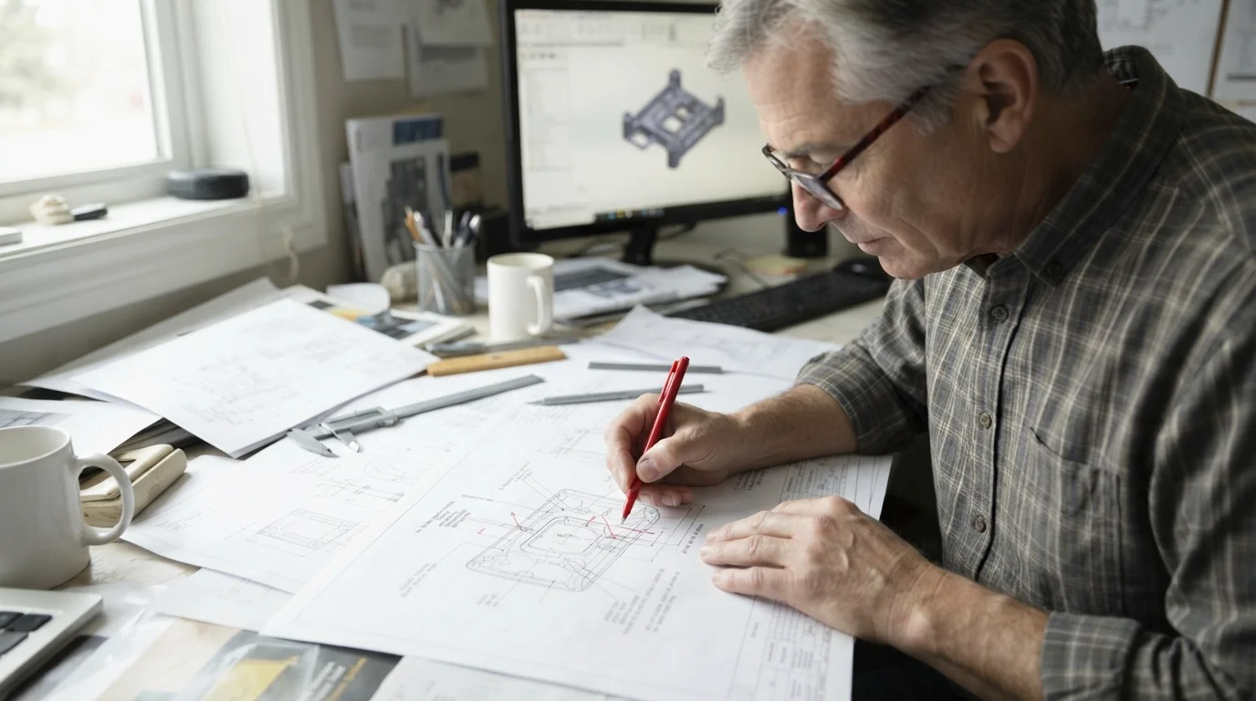
Las transiciones exitosas de prototipos visuales tempranos a producción de series cortas dependen en gran medida de optimizar las configuraciones del núcleo del molde antes de cortar metal. Los especialistas en fabricación evalúan líneas de partición, diseños de compuertas y posiciones de pasadores expulsores utilizando software avanzado de simulación de flujo de molde. Resolver posibles defectos de polímero y atrapamiento de aire durante los ciclos de diseño iniciales asegura que los componentes moldeados se liberen limpiamente sin defectos cosméticos. Los grupos de diseño de productos aseguran rutas de fabricación estables y rentables abordando sistemáticamente las reglas de escalado geométrico desde el principio.
Tabla de Contenidos
1. Cavidades de Metal Blando y Física de Transferencia de Calor en Utillaje Rápido
2. Líneas de Partición, Ubicaciones de Compuertas y Colocaciones de Pasadores Expulsores
3. Requisitos de Ángulo de Salida y Escalado Estructural a Alto Volumen
Cavidades de Metal Blando y Física de Transferencia de Calor en Utillaje Rápido
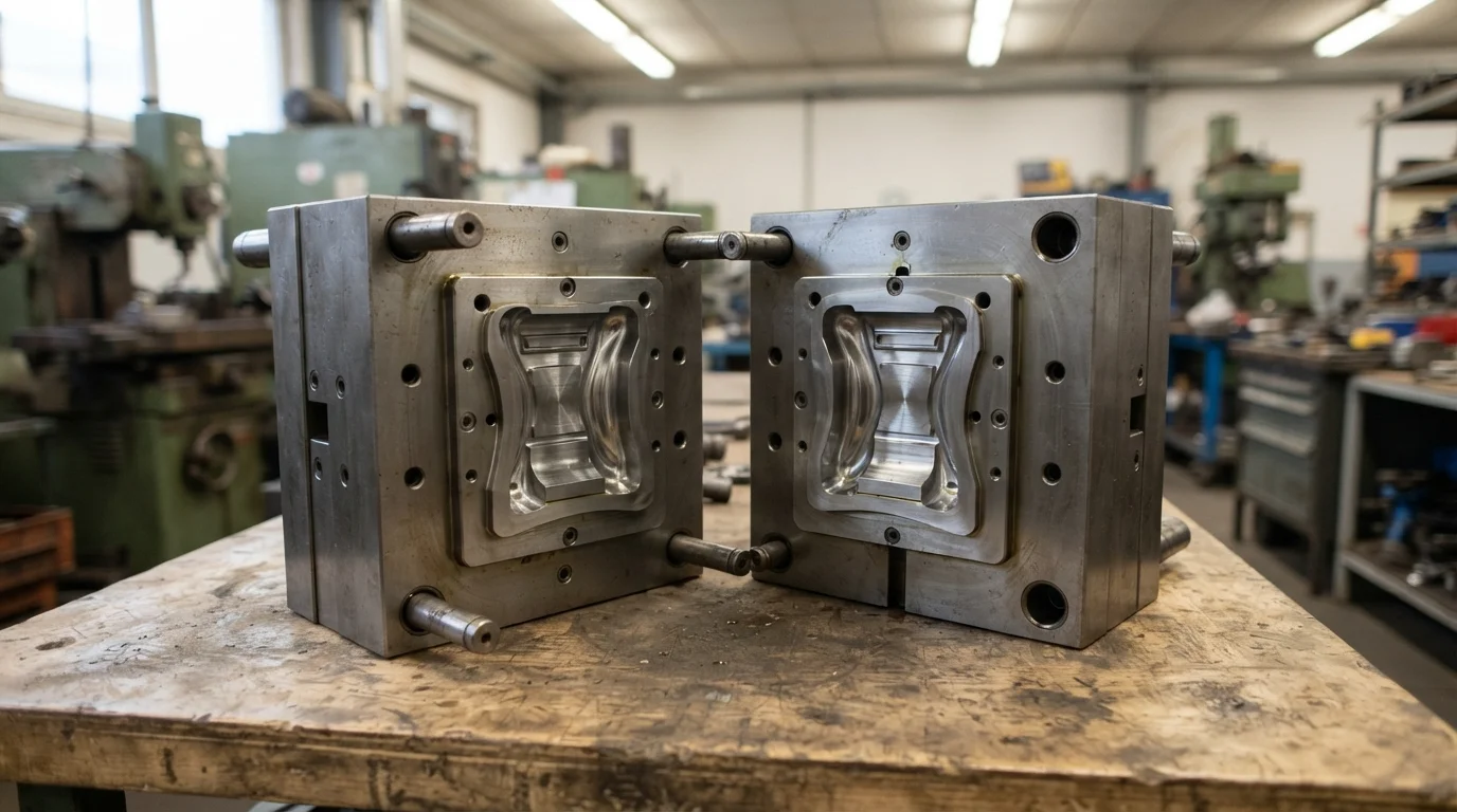
Pregunta: ¿Por qué los moldes de inyección de aluminio reducen los tiempos de enfriamiento en comparación con el utillaje de acero? Las aleaciones de aluminio exhiben valores de conductividad térmica hasta cuatro veces más altos que el acero para herramientas estándar, reduciendo la duración del ciclo de enfriamiento.
La selección de metales crudos para moldes influye directamente en los tiempos de ciclo de moldeo por inyección y en la estabilidad dimensional general de las piezas durante la producción de series cortas. Seguir reglas inteligentes de fabricación de moldes asegura que los ingenieros seleccionen aluminio QC-10 de alto grado o acero P20 blando para construir placas de molde rentables. La conductividad térmica superior del aluminio disipa el calor de los polímeros fundidos rápidamente, reduciendo drásticamente la duración de la fase de enfriamiento. Los ciclos de enfriamiento más cortos minimizan las tensiones internas localizadas, evitando que las paredes de plástico delgado se deformen durante la expulsión de la pieza.
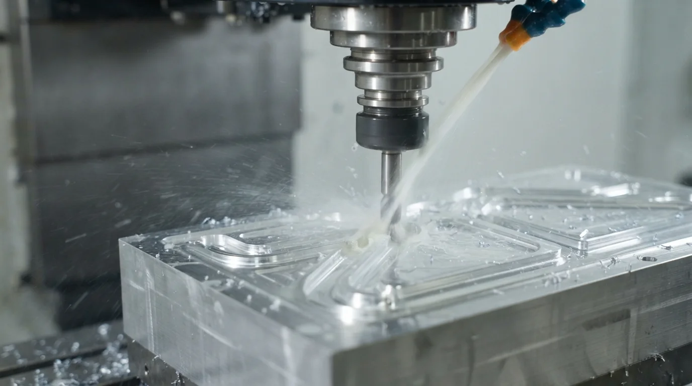
Las cavidades de aluminio QC-10 se mecanizan utilizando centros de fresado CNC de husillo de alta velocidad, eliminando múltiples configuraciones de electroerosión y acelerando la entrega del utillaje. Las cavidades de metal blando manejan resinas modificadas y rellenas de vidrio de manera eficiente para tiradas de producción de volumen medio de 10,000 a 100,000 componentes de manera segura. Obtener bloques de utillaje de aluminio reduce los gastos iniciales del molde hasta en un 70 por ciento en comparación con los moldes de producción tradicionales. Los diseñadores de utillaje analizan las divisiones de línea de partición temprano para asegurar que los cierres de aluminio blando resistan el desgaste bajo altas presiones de cierre.
Operar moldes bajo temperaturas de cavidad estables requiere integrar canales de agua de control térmico precisos directamente dentro de los núcleos del molde. Los canales de enfriamiento conformados enrutados en máquinas CNC de múltiples ejes siguen contornos de piezas complejos, manteniendo una uniformidad de enfriamiento absoluta. La reducción térmica consistente evita que los cubos de polímero gruesos o los cubos de tornillo sólidos se encojan de manera desigual. Obtener rutas de enfriamiento optimizadas ayuda a asegurar un costo de utillaje rápido altamente competitivo mientras se garantiza repetibilidades absolutas de las piezas.
Líneas de Partición, Ubicaciones de Compuertas y Colocaciones de Pasadores Expulsores
Pregunta: ¿Dónde deben ubicarse las compuertas de inyección en carcasas cosméticas? Colocar las compuertas en caras ocultas inferiores o estructuras de nervaduras internas oculta las marcas de corte y preserva el estilo exterior.
El plástico fundido ingresa a la cavidad del molde a través de compuertas precisas, dejando una marca delgada y visible que debe recortarse a mano o lijarse al ras. Los diseñadores de herramientas colocan compuertas de borde, subcompuertas o puntas de canal caliente en superficies no cosméticas para proteger la estética visual. El cizallamiento del polímero está altamente concentrado en las entradas de las compuertas, por lo que el dimensionamiento adecuado de estas es crítico para evitar la dispersión cosmética. La obtención de simulaciones completas de flujo de molde ayuda a los ingenieros a determinar las ubicaciones óptimas de las compuertas antes de cortar los bloques de metal en bruto.
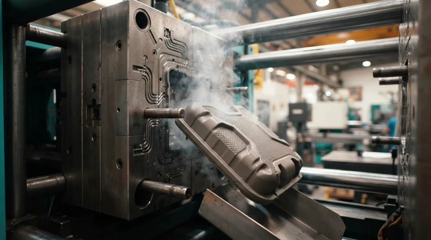
Los pasadores eyectores empujan físicamente la pieza de plástico solidificada fuera del núcleo del molde, dejando marcas circulares poco profundas en la superficie del polímero. Colocar los pasadores eyectores en caras de cubos interiores, uniones de nervaduras estructurales o paredes inferiores no visibles protege las superficies cosméticas visibles. Los diseñadores de herramientas equilibran la disposición de los pasadores eyectores simétricamente alrededor de geometrías complejas para evitar la torsión de la pieza o el blanqueamiento por tensión durante la eyección. La colocación simétrica de los pasadores asegura que la pieza se libere uniformemente del núcleo sin microgrietas.
Una planificación meticulosa de la línea de partición asegura que las uniones se diseñen a lo largo de límites geométricos naturales y afilados para simplificar la limpieza posterior al molde. El polímero fundido bajo alta presión de inyección puede escapar a lo largo de las líneas de separación, formando rebabas delgadas de plástico que requieren desbarbado manual. Los cierres de la línea de partición deben ajustarse a mano con precisión para evitar la formación de rebabas en uniones críticas. Esta tabla comparativa técnica destaca las diferencias de material y herramienta entre los estándares de molde base:
| Material de la herramienta | Conductividad Térmica | Vida útil típica de la herramienta | Aplicación principal de la herramienta |
|---|---|---|---|
| Aluminio QC-10 | 160 W/m·K | 10,000 a 100,000 ciclos | Moldeo puente de respuesta rápida, plásticos de bajo volumen |
| Acero blando P20 | 30 W/m·K | 100,000 a 500,000 ciclos | Carcasas de consumo de volumen medio, resinas modificadas con vidrio |
| Acero duro H13 | 24 W/m·K | Más de 1,000,000 de ciclos | Producción en masa de múltiples cavidades, polímeros altamente abrasivos |
Requisitos de ángulo de desmoldeo y escalado estructural para alto volumen
Pregunta: ¿Cuál es el ángulo de desmoldeo mínimo recomendado para moldes de inyección rápidos? Incorporar un ángulo de desmoldeo de 1.5 grados en todas las características verticales permite que el plástico moldeado se deslice libremente.
Las características verticales como nervaduras de refuerzo y salientes deben estrecharse ligeramente para permitir que las piezas se liberen limpiamente de las cavidades del núcleo. Las paredes sin ángulo de desmoldeo rozan contra el acero del núcleo bajo altas presiones de contracción, creando marcas de rozamiento visibles y grietas profundas por tensión. Incorporar un ángulo de desmoldeo mínimo de 1.5 grados en todas las características verticales permite que el plástico moldeado se deslice libremente. Los acabados texturizados especializados pueden requerir hasta 3 grados de desmoldeo para evitar el arrastre contra las cavidades del molde.
Calcular el costo integral de herramientas rápidas implica verificar los comportamientos de expulsión del molde bajo presiones reales de cierre de la máquina. Jucheng Precision apoya a los grupos de mecatrónica realizando revisiones DFM precisas para optimizar los perfiles de desmoldeo, los estilos de canal y los cierres de línea de partición. Tener tanto diseño de herramientas interno como treinta y cinco prensas de moldeo de alta precisión garantiza que reciba consejos completamente honestos y prácticos para reducir su costo general costo de prototipado rápido. Trabajar con un fabricante certificado bajo un mismo techo asegura que sus diseños transiten sin problemas desde los modelos conceptuales iniciales hasta la producción en serie.
Asociarse con un fabricante experimentado le ayuda a navegar la transición desde maquetas visuales tempranas hasta herramientas puente de bajo volumen sin problemas. Obtener sus cotizaciones manualmente garantiza que ingenieros experimentados analicen sus archivos 3D STEP para encontrar formas adicionales de ahorrar dinero en la fabricación de acero para moldes. Los componentes funcionales se someten a rigurosas verificaciones de metrología por coordenadas para confirmar el cumplimiento dimensional exacto. Obtener prototipos de alta calidad asegura que sus diseños estén construidos para soportar fuerzas dinámicas severas de manera segura.
Preguntas Frecuentes (FAQ)
¿Pueden los moldes de herramientas rápidas de aluminio manejar resinas modificadas con vidrio?
Los moldes rápidos de aluminio que utilizan QC-10 o aleaciones altamente resistentes al desgaste manejan resinas con vidrio de manera eficiente para tiradas medias de 10,000 a 100,000 piezas. Los componentes de la herramienta están diseñados con ubicaciones de compuerta robustas para minimizar el cizallamiento de fibras durante la inyección. Obtener revisiones DFM tempranas simplifica los diseños de líneas de partición, eliminando la necesidad de costosas acciones de molde.
¿Cómo se previene la deformación de las piezas durante el moldeo por inyección rápido?
Mantener espesores de pared uniformes es el método principal para prevenir la contracción diferencial y la deformación posterior al moldeo. Integrar canales de enfriamiento balanceados dentro de los bloques de cavidad de aluminio asegura una transferencia de calor uniforme en todas las características de la pieza. Los diseñadores de productos coordinan con especialistas en fabricación para aplicar acabados decorativos solo en las caras externas visibles.
¿Cuál es el plazo de entrega típico para un molde de herramientas rápidas de aluminio?
Los moldes rápidos de aluminio se mecanizan rápidamente en fresadoras CNC multieje, generalmente tomando solo de 10 a 15 días hábiles para completarse. Omitir los procesos lentos de electroerosión por chispa permite a los fabricantes entregar muestras moldeadas funcionales en semanas. Los diseñadores de moldes escalan los archivos 3D aproximadamente un 0.2 por ciento para compensar la contracción natural del polímero a medida que el plástico se enfría dentro de la cavidad.

