


Ultrasonic energy can melt polymer without creating a strong, sealed, or repeatable joint. Flash may hide incomplete fusion, the horn may scar a cosmetic surface, and dimensional variation may redirect energy away from the intended interface. Ultrasonic welding for medical devices works when material, joint geometry, molded condition, horn, fixture, trigger, process window, and inspection are developed together.
This article follows the energy path from the transducer to the joint. That perspective makes it easier to diagnose weak welds and to design components that can be assembled without relying on operator intuition.
Contents
Follow the Energy Path
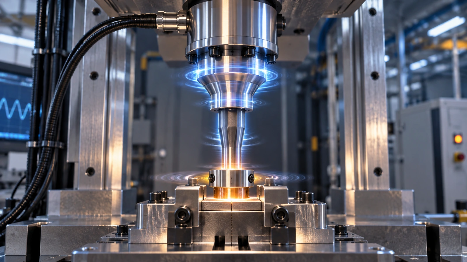
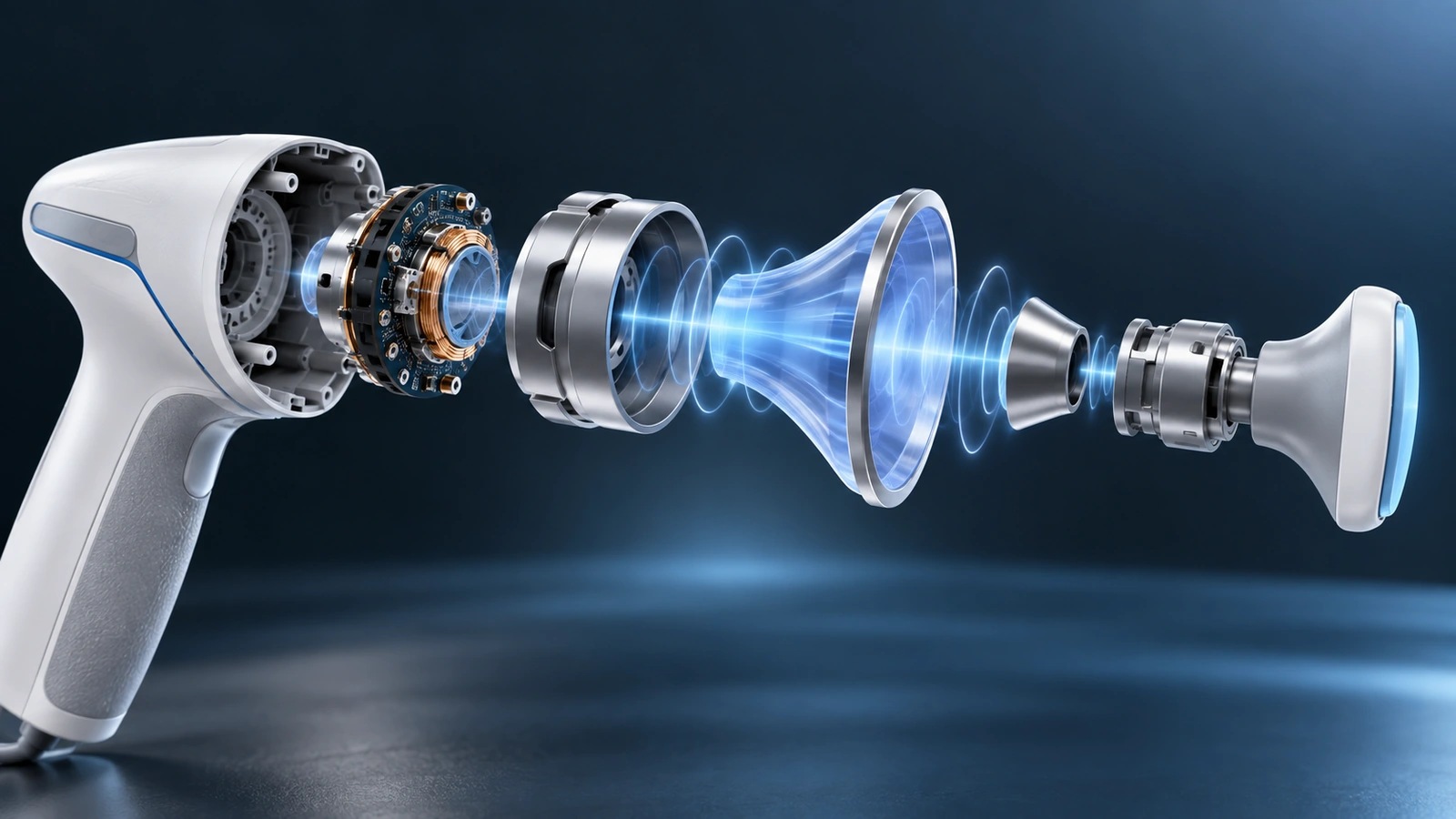
The machine generates high-frequency mechanical vibration. The converter, booster, and horn transmit it into the upper part while the fixture supports the assembly. Frictional and viscoelastic heating concentrate at the joint, melt the intended interface, and allow collapse under force. Hold time then lets the joint solidify under pressure.
Every interface along this path can waste or redirect energy. Poor horn contact, part curvature, flexible walls, weak fixture support, loose inserts, internal components, flash, and dimensional variation can change amplitude at the joint. Diagnose the complete stack rather than only changing weld time.
A successful ultrasonic weld is an energy-management problem before it becomes a machine-setting problem.
Ultrasonic joining is one option inside the broader medical device manufacturing processes portfolio. Compare it with adhesives, laser welding, thermal staking, solvent methods, mechanical fasteners, or redesign according to material, geometry, cleanliness, service, inspection, and volume.
Material Compatibility Is Grade-Specific
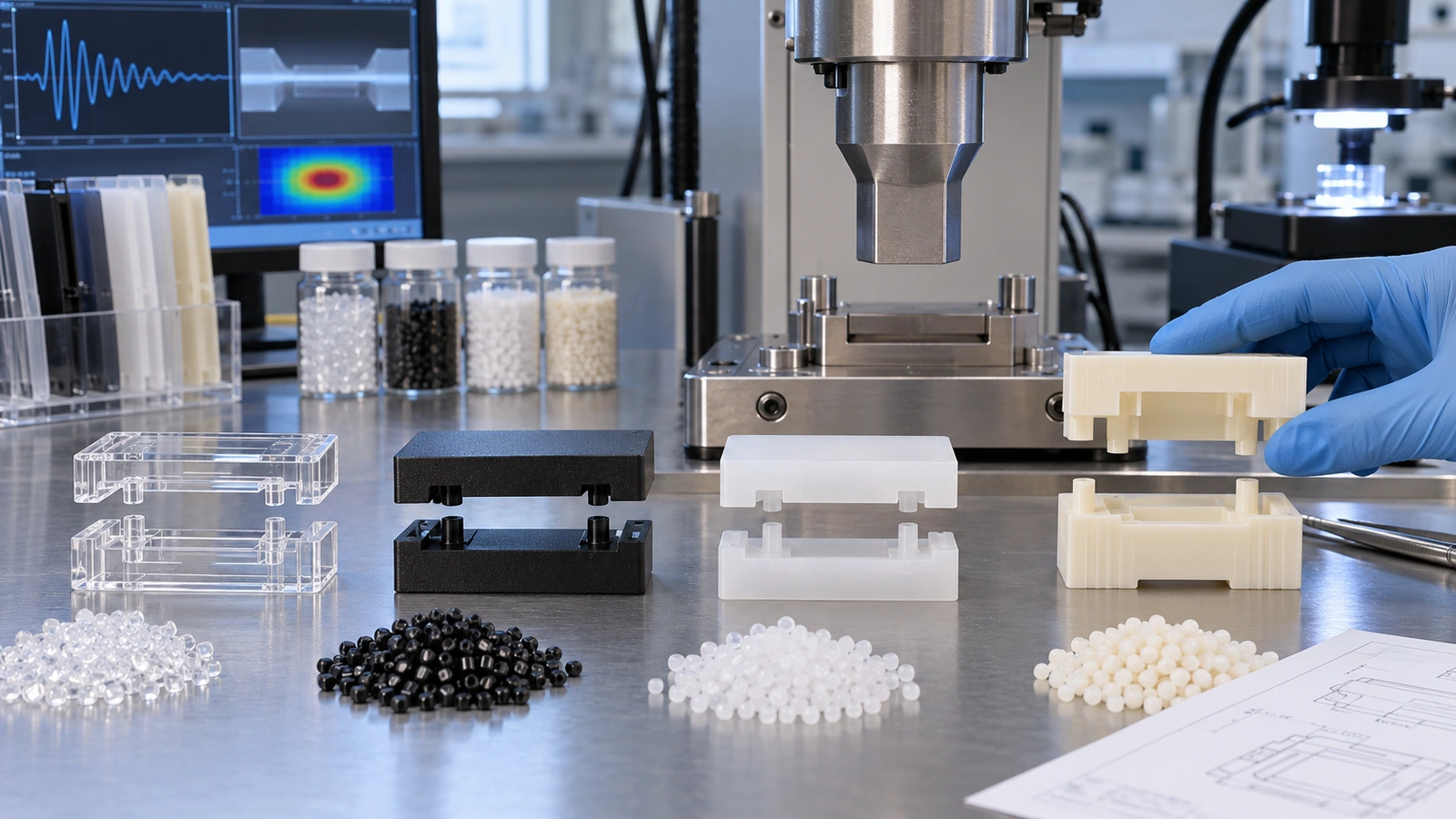
Polymer families differ in melting behavior, damping, stiffness, glass transition, crystallinity, moisture sensitivity, reinforcement, and additive response. Amorphous materials often transmit ultrasonic energy differently from semicrystalline materials. Similar family names do not guarantee equivalent weld behavior.
Use exact production grades, colors, fillers, and recycled-content policies during development. Glass fiber can alter stiffness, wear tooling, and influence local flow or weld strength. Flame retardants, impact modifiers, lubricants, and laser additives may change energy absorption. Moisture conditioning can also influence dimensions and welding response.
If two different polymers must be joined, evaluate their melting ranges, chemical compatibility, stiffness, and energy transmission. A mechanical capture, gasket, or alternative joining method may be more robust than forcing an ultrasonic process onto an incompatible pair. The medical device materials selection should therefore include the intended joining route.
The Joint Should Focus Energy Deliberately
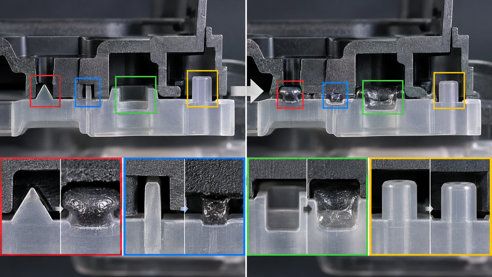
An energy director is a designed feature that concentrates initial contact and promotes controlled melting. Its geometry, location, continuity, and relationship to the load or seal path matter. A large flat interface without a focusing feature may require more energy and produce inconsistent melting.
| Joint feature | Propósito | Risk if poorly controlled |
|---|---|---|
| Energy director | Initiate and localize melt | Uneven fusion, excess energy, particulate, flash |
| Shear or step joint | Guide collapse and support seal path | Binding, misalignment, dimensional sensitivity |
| Flash trap | Contain expelled melt | Visible flash, particles, interference |
| Alignment feature | Locate components before welding | Preload, gap, joint offset |
| Collapse allowance | Permit controlled joint movement | Bottoming out or dimensional shift |
Keep sensitive components away from high vibration or provide support. Membranes, sensors, optics, filters, and delicate internal assemblies may require welding before installation or a modified sequence.
Horn, Fixture, and Part Stack
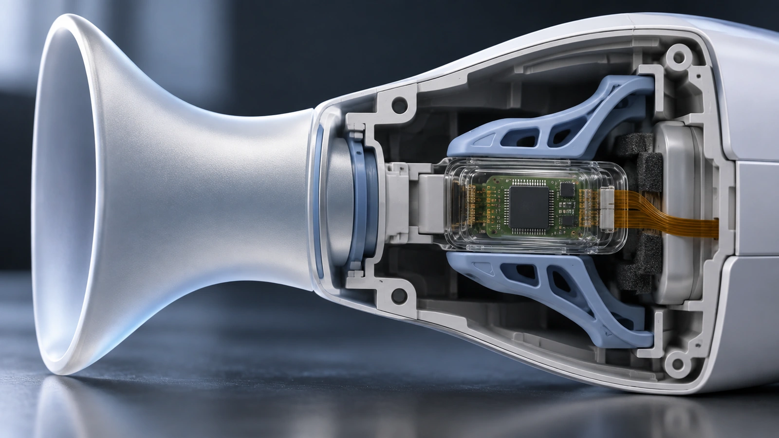
The horn should contact a stable surface and deliver amplitude without marking, slipping, or overstressing the part. Complex or large surfaces may need a contoured horn. The fixture should support the lower part close to the joint while allowing loading, unloading, and collapse.
Stack review checklist
- Horn contact area and cosmetic acceptance
- Part orientation and poka-yoke
- Fixture support under the joint
- Clearance for collapse and flash
- Internal-component protection
- Parting-line, gate, and ejector influence near the joint
- Tool wear, cleaning, and maintenance access
- Machine and stack tuning for the intended frequency
Molded-part variation enters the stack through warp, joint height, energy-director dimensions, and material condition. The tolerance plan should control the assembled interface rather than only isolated component dimensions.
Develop a Process Window
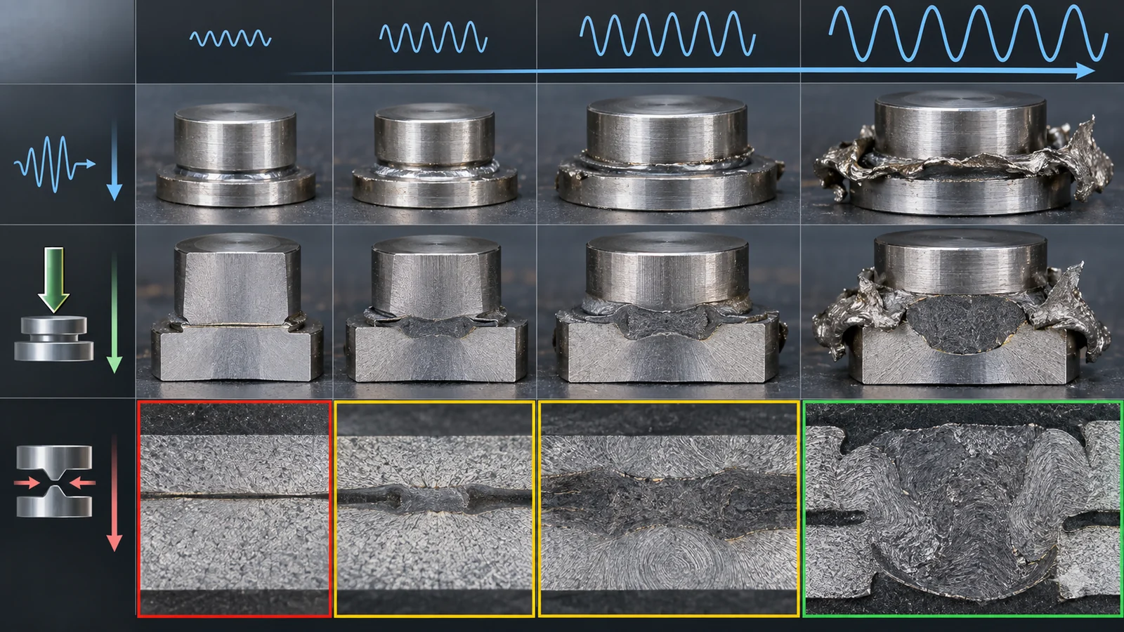
Common controls include amplitude, trigger force, weld force, energy, time, peak power, distance or collapse, hold force, and hold time. The most useful primary control depends on joint behavior and equipment. Limits should be based on product outputs, not copied from another assembly.
- Characterize the molded components and fixture stack.
- Run screening trials across meaningful settings.
- Measure collapse, strength, seal, flash, particles, dimensions, and surface damage.
- Challenge material lots, cavities, operators, and allowable part variation.
- Select a robust region and establish alert or reject limits.
- Lock recipes, tooling, software, and change authority.
Energy or power signatures can help monitor production, but a signature is meaningful only after it is correlated with acceptable and failed joints. A machine trace is not automatically proof of weld quality.
Inspect What the Device Needs
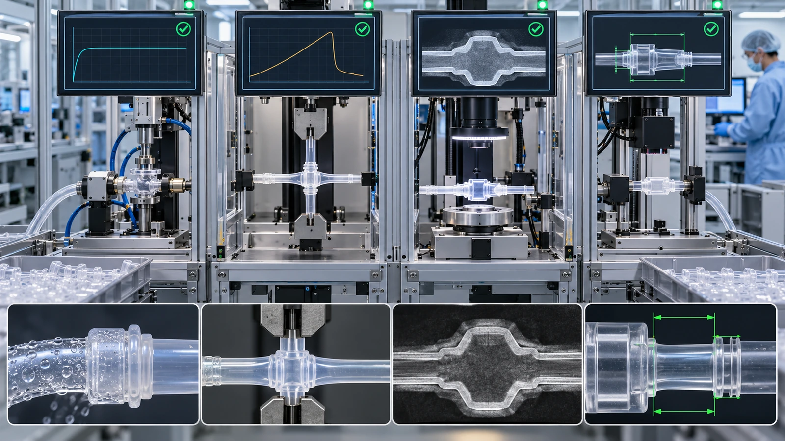
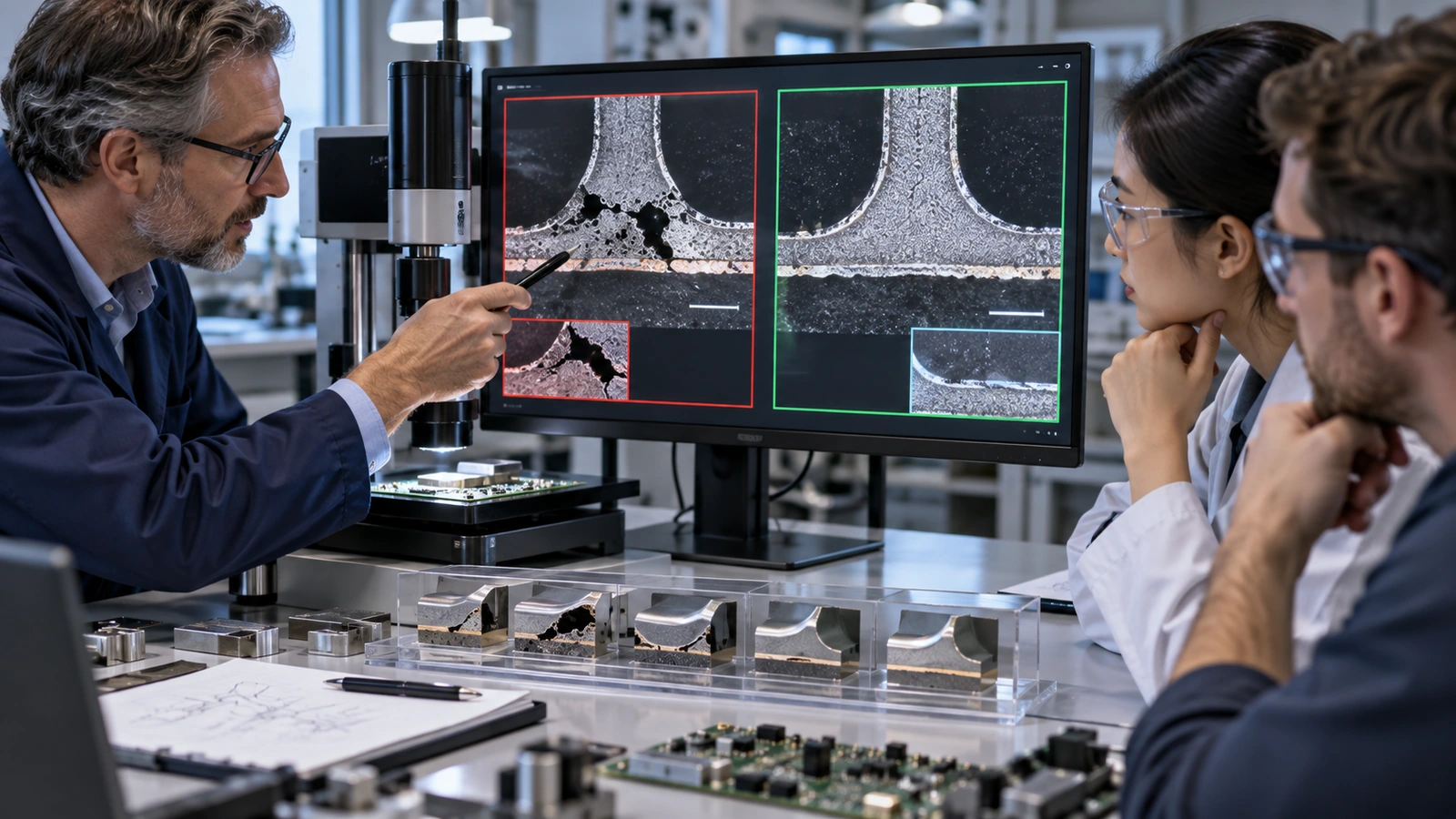
Inspection should follow the failure mode. Visual review can find flash, marking, cracks, misalignment, and gross collapse. Dimensional checks can verify assembled height. Leak or burst tests evaluate sealed systems. Pull, peel, torsion, or sectioning can characterize joint strength and fusion. Particles may require collection and analysis.
Destructive testing requires a sampling plan and representative specimens. A test fixture can create an unrealistic load path, so define how the instrument or device actually stresses the joint. For sealed fluid paths, test pressure, medium, dwell, temperature, and acceptance limit should reflect the requirement.
The quality-system context under medical device manufacturing standards connects test methods with records, equipment control, nonconformance, and lot release.
Validate and Monitor the Production Process
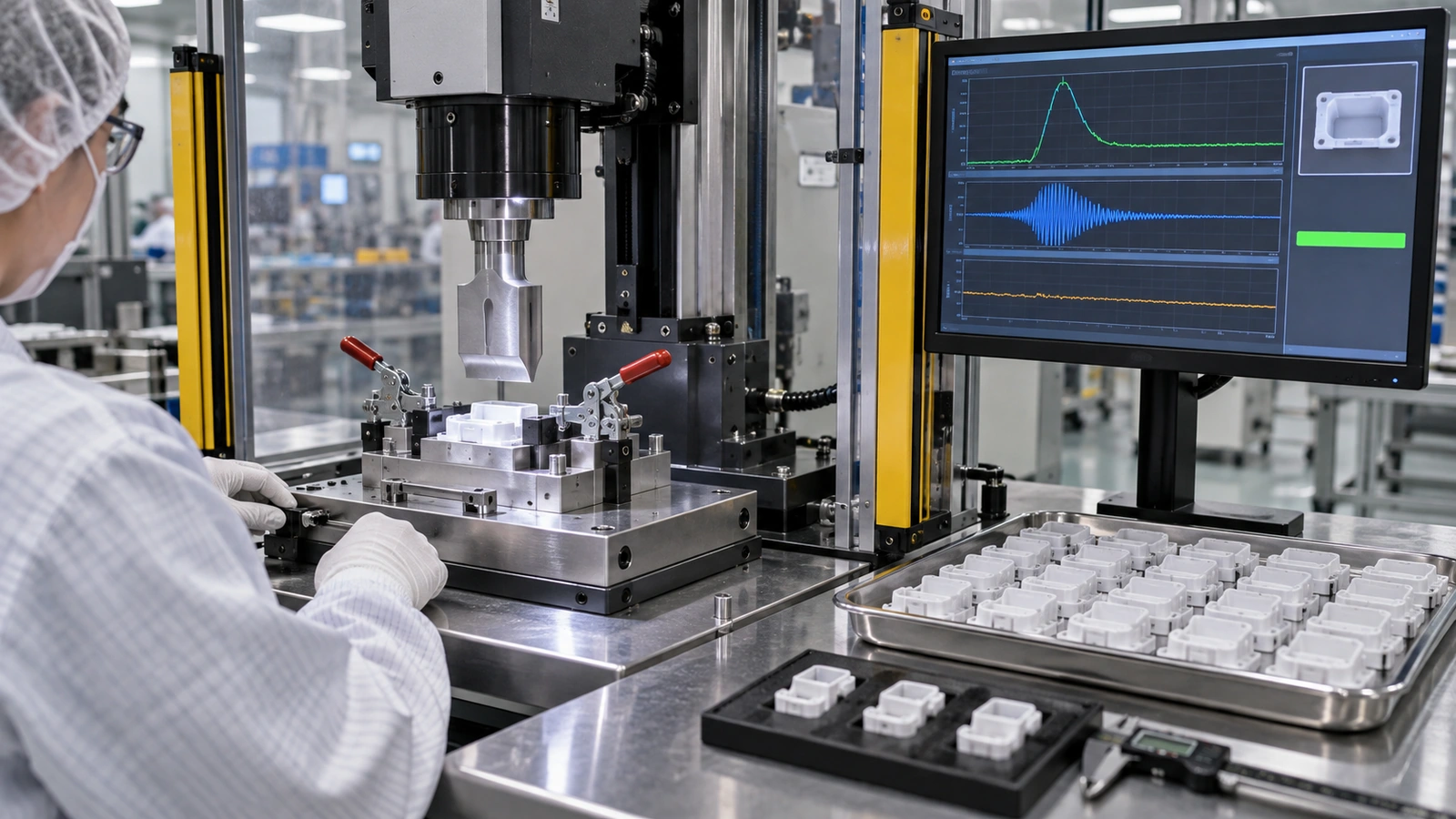
If the weld cannot be fully verified on every assembly without destructive testing, process validation may be necessary. Define equipment, horn, booster, fixture, material grades, molded-part conditions, software, recipe, environmental limits, operators, and inspection methods within scope.
Challenge supported high and low conditions and use production-representative parts. Predetermine acceptance, sample selection, analysis, and deviation handling. After release, monitor machine signatures and product outputs. Reassess after horn repair, fixture change, material or color change, mold modification, software update, equipment move, or recurring defect.
Validation establishes an approved state; maintenance, monitoring, and change control keep the process inside it.
Jucheng Development Support
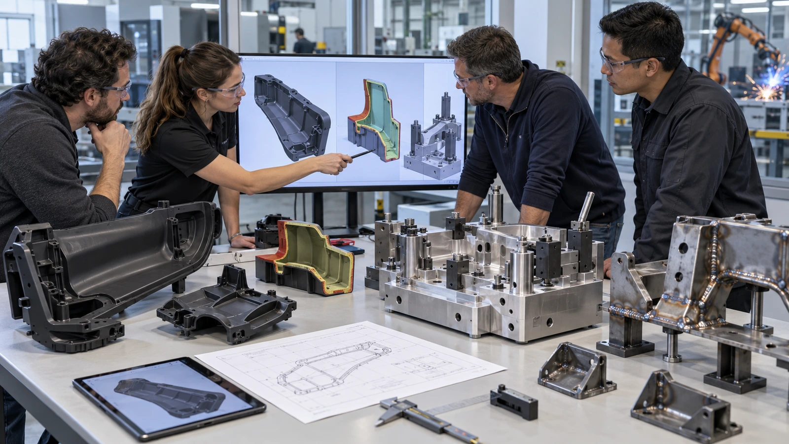
Jucheng Precision can support molded-part DFM, rapid tooling, injection molding, fixture components, assembly development, inspection, and controlled production. Reviewing the joint before tooling helps align energy directors, alignment features, cosmetic zones, tolerances, gate strategy, and fixture access.
Share exact resin grades, assembly models, joint function, seal or strength requirement, sensitive internal components, expected volumes, and evidence needs. Jucheng can evaluate whether ultrasonic welding fits the product and where prototype or molded trials are required.
Ultrasonic Welding FAQ
Can any two thermoplastics be ultrasonically welded?
No. Compatibility depends on exact grades, melting behavior, stiffness, damping, additives, geometry, and joint design. Dissimilar materials require specific evaluation and may need another joining method.
Why is there flash but low weld strength?
Energy may be melting the wrong area or expelling material without creating sufficient fusion. Joint geometry, gap, alignment, horn contact, fixture support, amplitude, force, and material condition should be investigated.
What does weld energy prove?
Energy is a process output that can support monitoring after correlation with product quality. The same energy can be dissipated through different paths, so it does not by itself prove strength or seal integrity.
Should the weld be controlled by time, energy, or distance?
The best control mode depends on joint behavior, equipment, and critical output. Development should compare how candidate modes respond to realistic variation and which one provides the most robust relationship to product quality.
Can ultrasonic welding damage internal components?
Yes. Vibration, clamp force, heat, particles, and movement can affect sensors, membranes, electronics, optics, or filters. Sequence, support, isolation, and representative testing are important.
Design the Energy Path Before Setting the Machine
Ultrasonic welding for medical devices is robust when material, molded geometry, joint, horn, fixture, process window, and inspection are developed as one system. A machine can deliver energy repeatedly; the design decides whether that energy creates the intended joint.
Send Jucheng your assembly files and joining requirements for DFM, tooling, and process-route review.

