


The big-end bore of a split connecting rod is an assembled feature. Its accepted geometry depends on the correct rod and cap, the specified fasteners and the defined assembly condition. Automotive connecting rod machining therefore needs a plan for the assembly before final bore finishing begins. Treating the cap as an interchangeable cover can undermine otherwise careful machining.
The discussion here concerns new drawing-based components and development parts. Reconditioning a used rod follows a different scope, with its own damage assessment and repair requirements. A new-part supplier should not assume that repair dimensions or resizing practices apply to a new design.
Receiving the blank establishes the route
A billet, a forging and another specified near-net blank can lead to different manufacturing routes. Their initial geometry, material condition, stock distribution and relevant records affect the operations that follow. The order should identify the intended starting form rather than leave the supplier to select a visually similar piece of metal.
For development, billet machining may permit geometry changes without dedicated forming tooling. That flexibility does not establish equivalence to a production forging. If the prototype is intended to support a performance decision, the design owner must determine which material and manufacturing differences are acceptable for that purpose.
Check where machining stock is available around both ends, the beam and the cap interface. A blank can contain enough total material while still lacking stock in the location needed to recover a critical feature. Plan the initial reference and evaluate the envelope before committing to subsequent operations.
The parent topic, automotive manufacturing processes, helps frame the route choice. This connecting-rod article narrows that discussion to one component whose two bores and split assembly must remain geometrically related throughout manufacture.
The cap interface is a manufacturing constraint
The design may use a conventionally machined joint, fracture separation or another specified arrangement. These are not interchangeable process choices. The joint form, locating features and assembly instructions must agree with the released design and the approved production route. Do not introduce a different separation method simply to simplify a prototype quotation.
Once a cap is matched to a rod, identification must survive the remaining operations. Establish how paired parts are kept together and how orientation is recognized. An identification scheme should be clear without damaging a critical surface or adding a mark in an unauthorized location.
Final bore work may require the specified assembly condition to be reproduced. The relevant fastener type, installation method and loading requirements belong in the manufacturing instructions. The supplier should obtain those requirements from the responsible design authority; a generic torque value from an unrelated engine is not an acceptable replacement.
Inspect the joint and locating features before assembly hides them. A final bore measurement can reveal a geometric result, but it may not explain whether a damaged interface, mismatched cap or assembly variation produced that result. Preserving intermediate evidence makes later diagnosis more useful.
If a thermal or surface process follows an early assembly check, decide what must be repeated afterwards. Passing an intermediate check only establishes the condition at that stage. The route should name the point at which the finished assembly is accepted.
Bring the small end into the same coordinate system
The two end bores must be evaluated as a relationship, not just as two acceptable diameters. Center distance, axis orientation, face relationships and the applicable geometric tolerances come from the drawing. Measuring each end in a convenient independent setup can miss a relationship that controls assembly.
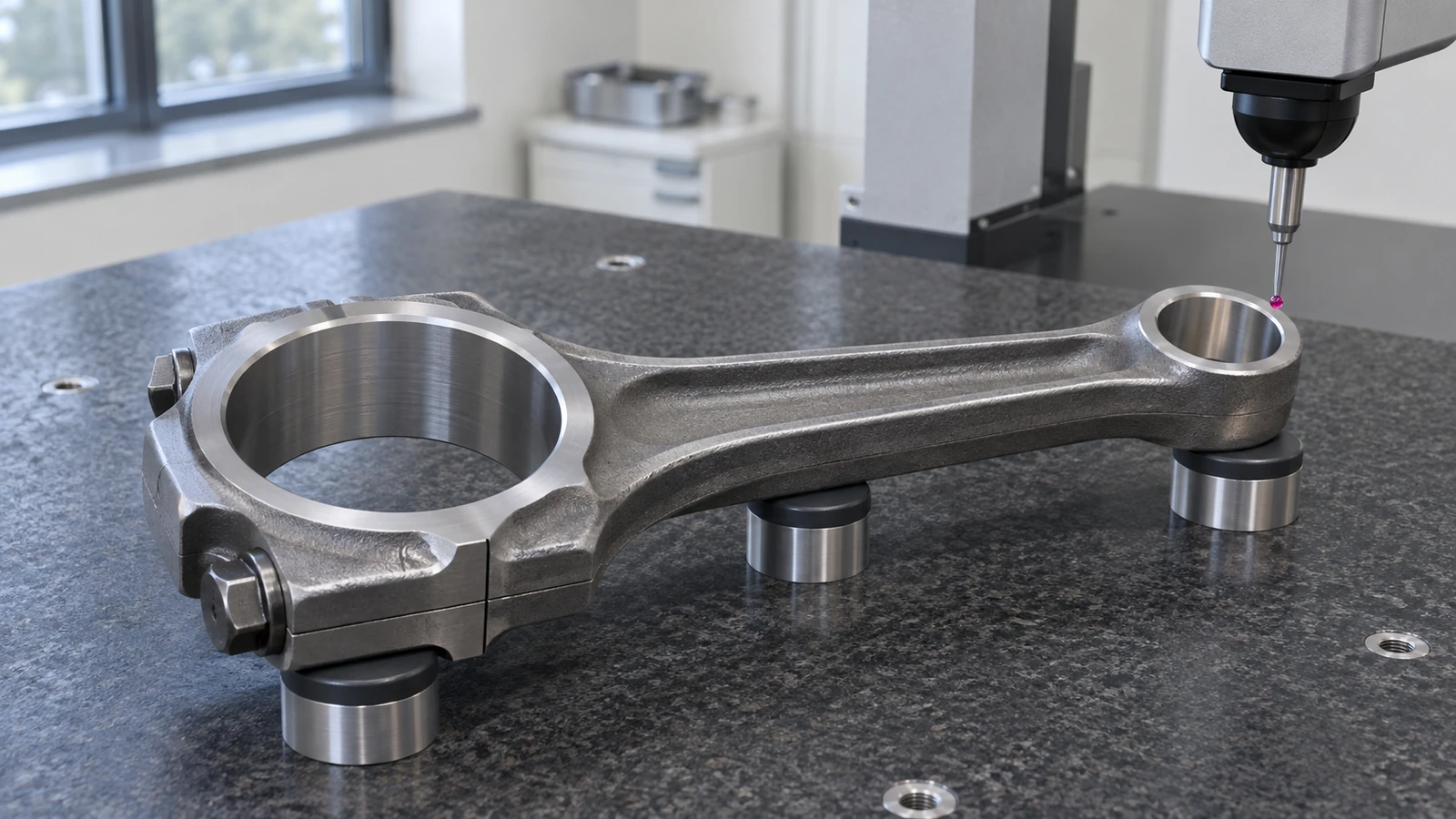
The small end may have a specified bushing or another bearing arrangement. If a bushing is part of the delivered assembly, distinguish the housing requirement from the installed and finished bushing requirement. An acceptable loose component does not automatically establish the condition after installation.
Define how the datum transfers between beam machining, end-face work and bore finishing. A location that is convenient during roughing may disappear later. Maintain sufficient reference features or provide an explicit transfer strategy so that finishing operations can be related to the required product definition.
Tooling suppliers also treat these features separately within an overall process. MAPAL鈥檚 connecting-rod application distinguishes small-end work, big-end work and bolt features. Its published application examples illustrate different machining demands; their numerical values should not be copied as universal tolerances for another rod design.
Schedule the irreversible operations deliberately
Rough machining removes stock while leaving material for later correction. Heat treatment or another required process may change the available finishing plan. The sequence must account for material condition and dimensional movement instead of assuming that every finished feature will remain stable through subsequent work.
When considering 4340 alloy steel machining, confirm that the grade and condition are actually specified for the design. A material commonly associated with demanding engine components is still not a universal selection. Stock form, heat treatment and traceability requirements need to be established for the individual order.
Workholding should support the beam and ends without hiding the free-state geometry. Local machining loads and clamping can affect a slender component differently at different stages. Intermediate inspection is useful when it answers a defined question, such as whether sufficient finishing stock remains or whether a datum relationship has shifted.
Controlled edge finishing is another irreversible step. Removing a burr differs from changing a designed fillet or blending away an unexplained surface indication. Describe the allowed finished geometry and escalate questionable conditions through the agreed review process. Appearance alone is not the acceptance standard.
If a specified treatment or inspection must be performed by an approved source, include that requirement in the quotation. A supplier鈥檚 general machining capability does not establish every external process approval needed for the order.
Release a set of evidence, not a collection of numbers
Start the final review with identity: the correct rod, matched cap, revision and material lot. Confirm the assembly condition used during inspection and the relationship between the measurement setup and the drawing datums. These details make the reported dimensions interpretable.
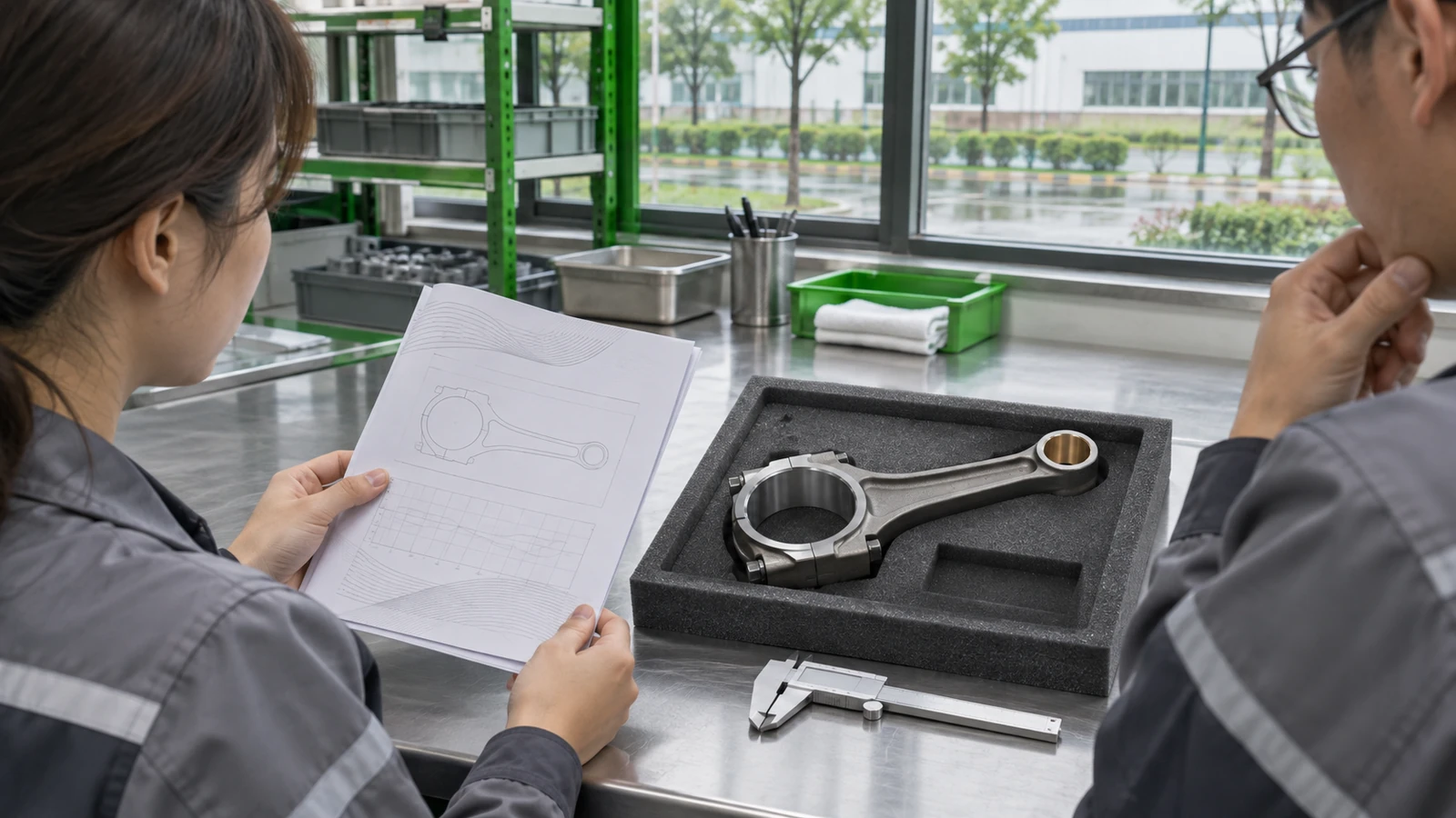
The report should distinguish local bore size from geometry and from the relationship between the two ends. It should also identify which characteristics were evaluated before assembly, after assembly and after any final treatment. A repeated result without its manufacturing stage can be misleading when the part changes between operations.
Where the order includes mass or set-matching requirements, agree on the actual method and allowable adjustment locations. Equal total mass does not, by itself, establish any separately required distribution or end-mass relationship. Do not remove material from a convenient area without authorization from the design definition.
A useful release review follows a few traceable connections: match the report to the component; match each result to the requirement; match the requirement to the correct revision; and match required process records to the actual lot. Missing information should be resolved before the set is packed.
Questions for a prototype purchase
Can one billet sample qualify a later forged design?
A billet sample can answer specific fit, access or manufacturing-development questions. Whether it supports a later performance claim depends on the design owner鈥檚 verification plan and the differences between the two routes. State the sample purpose and limitations before manufacture.
Can the cap be replaced with another cap of the same nominal size?
Do not assume interchangeability. The product definition and manufacturing method determine whether parts are matched and how a replacement can be accepted. Nominal size alone does not establish the complete joint and bore relationship.
What should accompany the request for quotation?
Provide the controlled drawing and model, blank specification, material condition, cap-interface definition, assembly requirements, quantities and inspection deliverables. Identify any customer-controlled operations and required special-process sources.
For Jucheng Precision鈥檚 Servicios de mecanizado CNC, this information supports a concrete scope review: which operations belong in the supplier鈥檚 work, which interfaces require clarification and what evidence will accompany the finished components. The resulting manufacturing proposal should make those responsibilities understandable before the first blank is cut.

