


A satellite optical bench is not simply a flat plate with mounting holes. It is the mechanical reference that keeps mirrors, sensors, cameras, or other optical elements in a defined relationship while the spacecraft experiences launch loads and a changing thermal environment. For a prototype or machined part, the useful question is therefore not only whether every feature meets its drawing dimension, but whether the manufacturing sequence preserves the alignment scheme the optical assembly depends on.
That distinction changes how engineers should define datums, choose stock, plan machining, and inspect the finished structure. A useful aviation and aerospace prototype review starts by identifying which surfaces establish optical alignment and which merely provide clearance or attachment.
Start with the optical reference scheme
Before selecting a cutter or a stock size, map the bench’s locating logic. Identify the primary mounting plane, the secondary orientation feature, and any tertiary stop or clocking feature. Then connect each optical mount to that datum reference frame. A hole pattern can be dimensionally correct relative to its own local center while still being misplaced relative to the instrument’s true alignment datum.
This is why a drawing review should distinguish functional features from convenience features. A mirror seat, kinematic interface, dowel bore, or sensor platform may control the assembled relationship. A cable tie point or noncritical relief usually does not. If every surface is marked critical, inspection becomes expensive and the design intent becomes harder to communicate. If no surface is identified as functionally important, the supplier may optimize a setup around the wrong face.
Where several optical devices share one bench, show how their axes relate. A section view or a coordinate table can make the intended relationship clearer than a dense collection of linear dimensions. The aerospace design for CNC machining page is a useful companion when reviewing access, datum choice, and feature arrangement before release.
Translate alignment into machinable geometry
Optical structures often combine broad reference faces, pockets, ribs, mounting pads, and closely positioned bores. Their difficulty comes from the interaction among these features. A thin web may reduce mass but leave a long surface vulnerable to movement during material removal. A deep pocket can improve packaging while limiting tool reach and making corner radii or floor thickness difficult to control. A raised pad may simplify assembly yet create a local stress concentration or a measurement-access problem.
Designers can make the part more manufacturable by keeping critical interfaces reachable from a practical setup, avoiding abrupt wall-thickness changes where possible, and specifying reliefs that a tool can actually cut. When a surface must remain a reference after machining, consider whether it should be finished in the same setup as its related bores or pads. Fewer setups can reduce datum-transfer error, but a single setup is not automatically best if the part’s size, tool access, or clamping force introduces distortion.
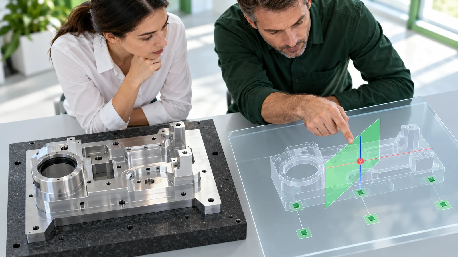
Do not convert an optical performance requirement into an unexplained machining tolerance. If the assembly needs a particular alignment, state the controlled feature relationship and provide the engineering basis through the drawing or interface control document. The supplier can then quote the manufacturing and inspection plan against the defined requirement instead of guessing at an arbitrary tolerance stack.
Choose a material for the real constraint
Material choice affects mass, thermal behavior, machinability, stiffness, and the stability of the finished geometry. Aluminum alloys are frequently considered for lightweight structures and can be practical to machine, but their thermal expansion and the component’s operating environment still matter. A lower-expansion alloy or a composite architecture may be appropriate for some optical systems, yet neither should be selected from a keyword list alone. The optical payload, temperature range, attachment method, coating system, and verification plan govern the decision.
Also distinguish bulk material properties from assembly behavior. A stable material does not prevent misalignment if the bench is clamped unevenly, mounted through incompatible interfaces, or connected to parts with different thermal response. Similarly, a material designation on a purchase order is not a substitute for the required condition, traceability, or documentation. Ask the design authority to state the exact material and condition; if alternatives are allowed, request approval before substitution.
For a first pass, compare candidate materials against mass, thermal stability, stiffness, machinability, joining, finish, and cleanliness requirements. The site’s aerospace materials overview can support the initial comparison, while final selection should remain tied to the controlled design definition.
Plan machining around distortion
A robust process plan balances stock condition, roughing, stress relief where specified, re-fixturing, finishing, and inspection. Roughing can remove a large share of material and change the balance of internal stresses. If the part is released from the fixture immediately after heavy cutting, a surface that looked flat under clamp load may move when unconstrained. A finishing pass should therefore follow the drawing’s datum strategy and the material supplier’s condition requirements, not a generic recipe.
Workholding deserves the same attention as toolpath strategy. A broad optical bench may need distributed support to avoid bending. Clamping on a thin wall can create a temporary shape that disappears after unclamping. Datum pads or sacrificial stock can help control the setup, but their removal must be sequenced so the remaining part stays supported. For a prototype, it can be useful to agree on an inspection hold point after roughing before the final finish pass.
Keep thermal management and tool deflection in view, especially on long cuts or slender features. The goal is not to prescribe a universal cutting parameter; those depend on alloy, tool, machine, geometry, and setup. Instead, identify the geometry most likely to move, and let the manufacturer propose a sequence that preserves the final reference relationships. The broader aerospace manufacturing process guide helps frame that process-selection discussion.
Inspect the relationship, not just the features
Inspection planning should mirror the alignment logic established at design review. A coordinate measuring machine can report the position of bores and planes relative to a datum frame, but the fixture and measurement method still need to represent the part’s functional mounting condition. If optical alignment is ultimately verified at assembly, component inspection should provide useful evidence without pretending to replace system-level optical alignment.
State how the part should be supported during measurement, whether it should be inspected free-state or under a defined restraint, and which features require a report. If a surface finish or coating is applied after machining, clarify whether dimensions refer to the pre-finish or finished condition and how masking boundaries affect the interface. These details can prevent a conforming machined component from becoming a nonconforming assembly because two teams used different measurement states.

For high-value interfaces, agree on a first-article review that includes the drawing revision, material records, critical dimensions, and any approved deviations. The aerospace quality and inspection guide provides a framework for connecting inspection evidence to the part definition.
What to send with an RFQ
A useful request for quotation includes the released 3D model and 2D drawing, material grade and condition, quantity, finish requirements, inspection expectations, and the revision that governs the quote. Add notes for optical datums, controlled interfaces, assembly orientation, and any surfaces that must be protected after machining. If a prototype is intended to validate only packaging or fit, say so; it should not be represented as flight-qualified hardware or as proof of performance beyond the tests actually performed.
Ask the supplier to identify assumptions before work begins: fixture strategy, datum transfer, proposed inspection method, finishing sequence, and any features that need clarification. That conversation is more useful than requesting a generic promise of “optical precision.” It exposes whether the part definition contains enough information to manufacture and verify the intended geometry.
Frequently asked questions
Is an optical bench always made from aluminum?
No. Aluminum is one possible choice, but the payload’s thermal stability, stiffness, mass, interface design, and mission environment determine the material system. Composite or lower-expansion options may be considered when the controlled design supports them.
Can machining alone guarantee optical alignment?
No. Machining can establish specified surfaces and feature relationships. Final alignment may also depend on mounting, assembly, adhesive or fastener behavior, thermal conditions, and system-level optical verification.
Which features should be inspected first?
Start with the datum features and interfaces that locate the optical assembly. Then inspect related bores, pads, and mounting patterns against that datum scheme, using a support condition consistent with the drawing.
Can a prototype prove flight readiness?
A prototype can answer defined design or manufacturing questions. Flight readiness requires the program’s approved verification, qualification, documentation, and acceptance process; a machined prototype alone does not establish it.

