


A UAV battery tray looks simple until the aircraft is accelerating, landing, or being serviced between flights. The tray must locate a pack, prevent unintended movement, leave room for wiring and connectors, and fit the airframe without consuming more payload space than necessary. A loose pack can shift the center of gravity; a tray that is too tight can make removal difficult or load the battery case in an unintended way. UAV battery tray manufacturing should therefore begin with the battery and aircraft interfaces, not with a generic flat plate.
The manufacturing route depends on whether the design is a lightweight structural carrier, a protective enclosure, or a replaceable battery module with rails and latches. This article focuses on the mechanical part: how it is positioned, supported, made, and checked. It complements the wider drone and UAV parts machining work without implying that a tray itself defines battery electrical or flight-safety performance.
Freeze the pack envelope and removal path
Start with the actual battery pack or a controlled model that includes its case, terminals, connector, cable exit, labels, and any intended protective sleeve. Nominal length and width do not capture every feature that can interfere with a tray. Connectors may project farther than the housing, and cable bend space may dictate the direction of insertion. If a pack is replaced by hand, define the grip surfaces and the space needed for fingers; if it is secured with a tool, include tool access.
The removal path should be treated as a three-dimensional envelope. A pack that fits when the top plate is absent may collide with an arm, landing structure, or adjacent electronics during real installation. Model the path from the entry position to the fully seated position, including rails, latch travel, and connector engagement. This can reveal whether the design needs a removable crossbar or a different latch location before tooling begins.
Do not use a manufacturing tolerance as a substitute for a defined service clearance. Battery cases, soft sleeves, and connector bodies can vary, while dust or minor surface damage can increase friction. The design owner should specify the permitted movement, insertion force or user method if known, and the allowed clearance range. Those values should come from the actual battery and aircraft requirements rather than a generic recommendation.
Design retention around load direction
The tray needs to restrain the pack in the directions that matter during flight and handling. A bottom surface may support weight, but side guides, end stops, straps, clips, or a latch may be needed to prevent translation and lift. Retention should be evaluated for forward acceleration, lateral maneuvering, vibration, landing shock, and service handling as defined by the program. A single strap may be quick to prototype but can cover labels or connectors and may relax over repeated use.
Avoid concentrating load on a thin battery-case wall or a small corner unless the pack design allows it. Broad contact pads can distribute pressure, while compliant inserts may protect surfaces or accommodate dimensional variation. However, a soft pad can compress over time, absorb contaminants, or change friction. If an insert is used, identify its material, thickness, attachment, and replacement method so it is not treated as an undocumented assembly aid.
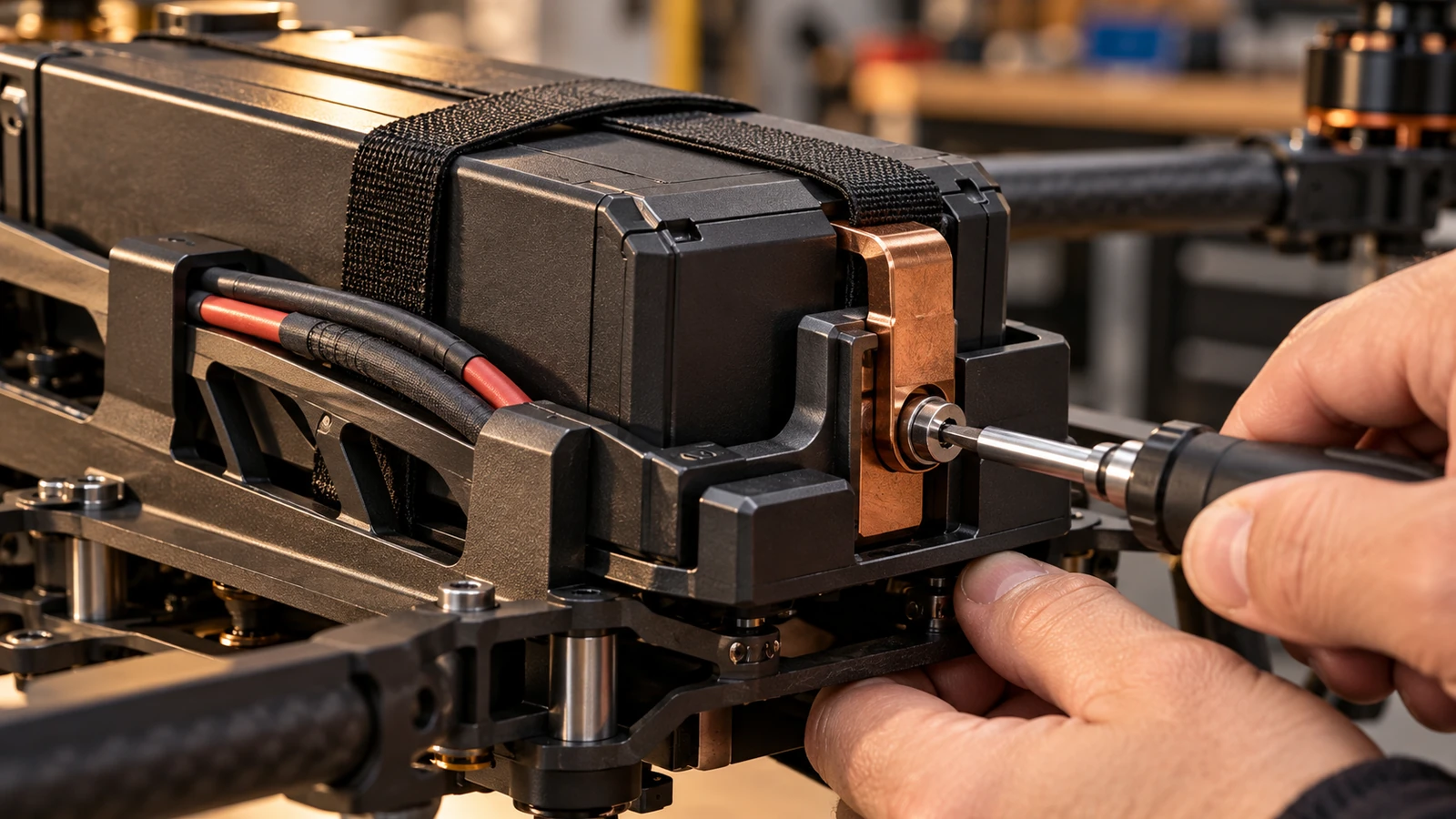
Latches and fasteners should have a visible, inspectable state. A hidden clip can be difficult to verify during a fast pre-flight check. A screw that requires a loose nut may be inconvenient in field service. A captive fastener or a clear latch stop can improve usability, but adds features that affect fabrication and assembly. Review the retention mechanism with the person who will install and remove the pack, not only with the designer viewing CAD.
Match the tray to the airframe structure
A battery tray is part of the aircraft load path when it transfers pack loads into the frame. Identify the support points, fastener pattern, and surfaces that establish the battery position. If the tray bridges two frame members, its stiffness and attachment spacing can influence deflection. If it is a small cradle attached to a composite or molded structure, the mating design must respect the airframe’s local thickness and load limits. Those limits should come from the airframe design authority; do not infer them from a photograph.
The tray can also influence center-of-gravity adjustment. Slots or multiple mounting positions may allow configuration changes, but they can make assembly orientation ambiguous. Marking, keying, or a clearly asymmetric hole pattern can reduce the risk of installing the tray in the wrong position. If the battery position is a controlled flight parameter, identify the datum and dimension that set it so inspection does not rely on visual estimation.
Cable routing deserves the same attention. A tray edge should not abrade insulation, and the connector should not be forced into a bend by the retention feature. Add radiused edges or guards where needed and ensure the harness can be secured independently of the battery. These details are especially useful to review with adjacent parts and the broader UAV prototype before the final tray geometry is released.
Select a process for the build stage
CNC machining can suit a rigid metal tray with controlled mounting faces, slots, rails, or local pockets. Sheet metal can work for a formed carrier when the geometry is mostly panels and flanges. Additive manufacturing can provide a fast way to test packaging, latch placement, or a complex polymer guide, while injection molding may be considered after the design and expected volume justify tooling. A route that is suitable for one prototype may not be the best choice for repeated production.
| Build question | Potential route | What it can help evaluate |
|---|---|---|
| Are mounting datums and metal interfaces correct? | CNC-machined prototype | Fit, local stiffness, fastener access, and machined interfaces |
| Can a panel-and-flange layout hold the pack? | Sheet metal prototype | Bend layout, assembly sequence, and service access |
| Does a complex polymer retainer package correctly? | 3D-printed prototype | Envelope, latch concept, cable clearance, and ergonomics |
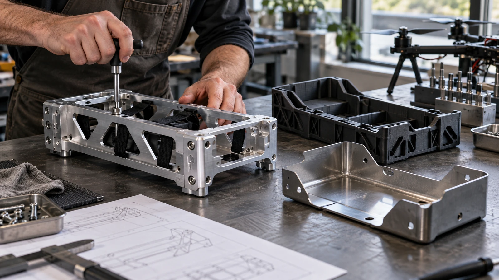
A prototype should not be treated as proof of every production property. A printed polymer part may validate dimensions and access but not long-term creep or impact behavior. A machined aluminum tray does not prove that a later molded polymer design will hold the same fit. State which tests a prototype will support, and which need a production-representative part.
Compare materials without assuming one winner
Aluminum can offer a light, rigid platform and practical machined mounting features. Steel may be considered where a formed bracket needs a particular stiffness or wear behavior, though the mass trade-off must be evaluated at aircraft level. Engineering polymers can create integrated guides, clips, or protective features, but their behavior depends on grade, temperature, moisture, loading duration, and manufacturing process. A flexible liner may protect a pack while a separate rigid frame carries the structural load.
For prototypes, nylon can be useful for some complex geometries, while polycarbonate may be considered where impact behavior or a different stiffness profile is relevant. The exact grade and process matter; a generic material label is not a complete specification. Review the site’s aluminum machining material information y nylon machining page as starting points, then confirm the real part requirements and finish.
If the tray is near electronics or a battery, thermal behavior, electrical isolation, corrosion exposure, and cleaning needs may influence the choice. Avoid assuming that a coating provides a complete environmental barrier or that a polymer component is automatically electrically safe. The design specification should say what the tray must do and what system tests establish that it does so.
Verify fit, access, and repeatability
Inspection should check the features that control pack location and restraint: mounting-hole position, guide spacing, stop height, latch engagement, and relevant datum relationships. A simple fixture can make repeated checks more consistent, but it should locate the tray from the same surfaces used by the aircraft. If the tray is measured loose on a table, an out-of-plane condition may go unnoticed until installation.
Functional verification can include an installation trial with a representative battery, confirmation that the retention feature reaches its intended state, a cable-routing review, and removal with the expected tools or hand motion. If the program calls for vibration, shock, thermal, or flight testing, those tests need a defined plan and responsible owner. The manufacturing inspection report is evidence about specified dimensions; it is not a substitute for aircraft-level validation.
For a family of trays, control revisions and interchangeable components. A change in pack supplier, case geometry, connector location, or airframe attachment may invalidate earlier fit evidence. Record the drawing revision, material, finishing state, and any approved deviation for each build so a replacement tray can be compared on the same basis.
Prepare a drawing package suppliers can quote
An RFQ should include the tray model and drawing, pack envelope, airframe mating geometry, material and finish, quantities by stage, critical dimensions, retention concept, and any test or inspection expectations. Show the battery connector and cable exit, not just the outside shell. Identify whether the supplier is expected to make a prototype, a short pilot lot, or a repeat batch.
Call out controlled features such as the pack datum, rail spacing, latch stop, mount pattern, and masked or coated surfaces. Ask for a DFM review of thin sections, inaccessible corners, tool access, bend feasibility, fastening, and inspection setup. If key design choices are unresolved, identify them as open questions instead of presenting a preliminary model as a released production definition.
A dependable UAV battery tray is a coordinated interface: it secures the pack, respects the airframe, supports service, and can be inspected against clear requirements. The strongest starting package includes the real battery, representative airframe geometry, and a defined installation task, allowing the manufacturing process to support the aircraft program rather than forcing the program to adapt to an arbitrary tray.

